Wind Turbine Gear Ratio Calculator
Match a wind turbine rotor to a generator target RPM using rotor RPM, TSR wind speed estimates, pulley or sprocket sizes, drivetrain efficiency, torque input, and slip.
Start with a common small-wind setup, then adjust rotor speed, generator target, sprocket or pulley sizes, slip, efficiency, and torque for your turbine.
Wind Turbine Gear Ratio Results
These results compare the required speed increase to your pulley, sprocket, gearbox, or direct-drive setup, then estimate output RPM, torque change, TSR, and shaft power after losses.
| Item | Formula | What it means | Watch point |
|---|---|---|---|
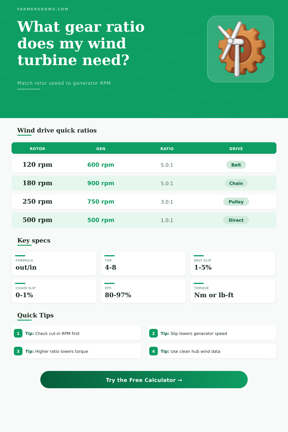
| Required ratio | Generator target RPM / rotor RPM | Speed increase needed before slip is considered | Generator cut-in RPM often sets the minimum |
| Pulley or sprocket ratio | Driver size / driven size | Large rotor pulley to small generator pulley raises RPM | Use matching units or tooth counts |
| Output RPM | Rotor RPM x ratio x (1 - slip) | Expected generator shaft speed after speed loss | Belt slip can move a close match below target |
| Torque output | Rotor torque x efficiency / ratio | Speed increase trades torque for RPM | High ratios may reduce starting torque |
| Shaft power | Torque x RPM / 9550 | Metric shaft power in kW when torque is N-m | Losses reduce deliverable generator power |
| Rotor driver | Generator driven | Mechanical ratio | Example use |
|---|---|---|---|
| 8 in pulley | 4 in pulley | 2.00:1 | Small alternator with moderate rotor RPM |
| 12 in pulley | 3 in pulley | 4.00:1 | Fast PMA from a slower blade set |
| 60 tooth sprocket | 12 tooth sprocket | 5.00:1 | Compact chain step-up drive |
| 72 tooth sprocket | 18 tooth sprocket | 4.00:1 | More tooth engagement than a tiny sprocket |
| 10 in to 2 in, then 6 in to 3 in | Two stages | 10.00:1 | High RPM generator with belt wrap control |
| Blade style | Typical TSR | RPM behavior | Generator match note |
|---|---|---|---|
| Savonius or drag rotor | 0.8 to 1.5 | Slow and high torque | Often needs large step-up or low-RPM generator |
| Farm-built three blade | 4 to 6 | Moderate speed band | Usually works with belt or chain step-up |
| Small efficient HAWT | 6 to 8 | Fast tip speed | May need less ratio than wide slow blades |
| Direct-drive axial flux | 5 to 7 | Designed around rotor speed | Coil count and magnets replace gearbox ratio |
| High-wind furling rotor | Varies | Speed limited by control | Use operating RPM, not survival gust RPM |
| Drive setup | Efficiency range | Slip range | Planning note |
|---|---|---|---|
| V-belt step-up | 85% to 94% | 1% to 5% | Good belt wrap and tension keep output RPM steady |
| Timing belt | 90% to 96% | 0% to 1% | Accurate speed, but alignment and tooth load matter |
| Roller chain | 92% to 97% | 0% to 1% | Low slip with lubrication and guarded moving parts |
| Small gearbox | 80% to 96% | 0% | Check start torque and cold oil drag |
| Direct coupling | 95% to 99% | 0% | Best when generator RPM target matches rotor RPM |
This calculator is for drivetrain planning. Final turbine designs should also account for blade control, braking, tower loads, overspeed protection, guards, and generator documentation.
A small wind turbine often sits on a ridge or behind an barn. A small wind turbine will rarely spin at the same speed as the generator that is inside teh housing of the turbine. The blades of the rotor will turn slow due to there design to catch the wind.
However, the generator will need to spin at hundreds or even thousands of revolution per minute. Thus, a person will need to plan the gear ratio for the setup. Planning the gear ratio ensure that the small wind turbine can bridge the gap between the small speed of the rotor and the high speed of the generator.
How to Choose the Right Gear Ratio and Drive for a Small Wind Turbine
Due to the difference in the speeds of the rotor and the generator, there will be a difference in the amount of torque that reaches the generator. The gear ratio must provide an increase in the speed of the rotor to ensure that the generator can reach its cut-in point for energy production. However, if the gear ratio increases the speed of the rotor too much, the rotor will not have enough torque to overcome any friction in the system.
Thus, a person will need to find a balance in the gear ratio between the requirement of the rotor and the generator as well as the need for sufficient torque to overcome any friction. The speed of the rotor can be measured in two ways. A person can use a tachometer or a phone application to measure the speed of the rotor.
Alternatively, a person can calculate the speed of the rotor by calculating the tip speed ratio of the turbine, the diameter of the rotor, and the speed of the wind at the site. These two methods help provide an understanding of the amount of mechanical advantage that will be needed to connect the rotor to the generator. A person will also have to decide on the type of drive system that they will use.
For example, belt drives are easy to install and repair but lose some of the speed of the rotor. Chain drives retain most of the speed of the rotor but require regular lubrication. Gearbox drives retain most of the speed but lose some of the starting torque of the rotor.
Lastly, a direct drive system does not lose any of the speed of the rotor but only works if the generator has the same speed as the rotor. Another variable that will reduce the speed of the rotor is the slip of the drive system. For instance, if a belt drive system is implemented with light tension on the belt, the system can lose two or three percent of the speed of the rotor before it is transmitted to the generator.
This loss of speed can reduce the rotor to the point where it cant charge the battery. Thus, a person must take into account any possibility of slip in the selection of the drive system. The movement of the rotor is in the opposite direction of the movement of the speed of the rotor.
Thus, if a person increases the gear ratio to boost the speed of the rotor, the same amount will reduce the torque. This loss of torque can make it difficult for the rotor to start the wind turbine as the rotor may have enough torque to turn when the wind is strong but may not have enough when the wind is light. Thus, a balance has to be found between speed and torque.
In the drivetrain of the small wind turbine, there will be efficiency losses in the bearing, the belt, the chain, and the gearbox. The efficiency of each component may appear high when considered individually but the efficiency of the entire system will drop when all the components are taken into consideration. These efficiency losses will result in the creation of heat within the machine as well as a reduction of the amount of power that can be delivered to the battery or inverter.
Thus, when planning the drive system, a person should consider the efficiency of each component. Another factor to consider for any small wind turbine is the tip speed ratio. A rotor that is designed to have a tip speed ratio of six will move at a faster rate than a rotor with a tip speed ratio of four.
This increased rate of movement will allow for a decrease in the gear ratio that is required to place the rotor and the generator in relationship to one another. Thus, the tip speed ratio is one of the factors that should be considered when building the turbine. The wind speed will not remain constant throughout the year.
The gear ratio for the turbine should account for both high and low wind speeds. While the overspeed protection will manage the high wind speeds for the machine, the gear ratio should account for the low wind speeds to ensure the rotor has enough torque to start the generator. Once the rotor is turning at the right speed for the generator, a person must focus on the rest of the system.
For example, the rotor must have a pitch or furling system to handle storms. Additionally, the electrical components of the machine must be constructed in a way that they can carry the current without creating a loss of that current. Thus, while the gear ratio is only one part of the system, the planning of that gear ratio will remove a large variable in the system that can lead to underperformance of the small wind turbine.
If the rotor and the generator are turning at the proper speeds for the component being manufactured, the small wind turbine will have a more better chance of performing as intended.