Vertical Wind Turbine Calculator
Estimate vertical-axis wind turbine output from rotor height, diameter, swept area method, wind speed, air density, turbine Cp, generator efficiency, RPM or TSR, and array spacing.
Choose a realistic farm or homestead starting point, then adjust rotor geometry, wind speed, coefficient of performance, generator efficiency, TSR, and array spacing.
Vertical Wind Turbine Results
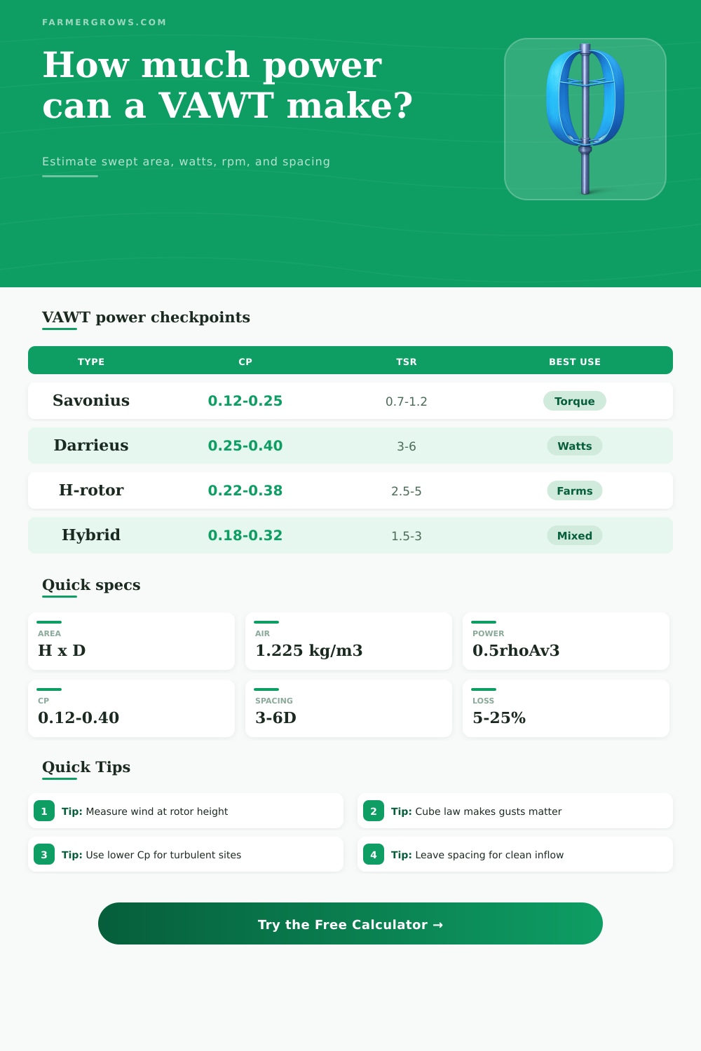
Outputs use Pwind = 0.5 x air density x swept area x wind speed cubed, then apply Cp, generator efficiency, and array losses.
| Step | Formula | Calculator input | Meaning |
|---|---|---|---|
| Swept area | A = H x D | Rotor height and diameter | Projected VAWT rectangle facing the wind. |
| Wind power | Pwind = 0.5 x rho x A x v³ | Air density, area, wind speed | Total kinetic power passing through the rotor area. |
| Rotor power | Protor = Pwind x Cp | Selected VAWT type or custom Cp | Power captured by blades before generator losses. |
| Electric power | Pe = Protor x efficiency | Generator and drivetrain percent | Estimated usable electrical output per turbine. |
| Daily energy | kWh = W x hours / 1000 | Useful wind hours per day | Equivalent energy for battery or farm load planning. |
| Array energy | Single kWh x count x loss factor | Turbines and loss percent | Farm-row output after wake and wiring losses. |
| VAWT type | Typical Cp range | Typical TSR | Farm planning note |
|---|---|---|---|
| Savonius drag rotor | 0.12 to 0.25 | 0.7 to 1.2 | Good startup torque for small chargers and turbulent sites. |
| Darrieus eggbeater | 0.25 to 0.40 | 3 to 6 | Better efficiency in cleaner wind; startup help may be needed. |
| H-rotor lift turbine | 0.22 to 0.38 | 2.5 to 5 | Useful straight-blade layout for farm-built prototypes. |
| Hybrid rotor | 0.18 to 0.32 | 1.5 to 3 | Balances startup behavior with moderate running efficiency. |
| Conservative rough-air estimate | 0.10 to 0.20 | Use measured | Better for low masts near trees, barns, bins, or uneven terrain. |
| Average wind | Power vs 5 m/s | Site interpretation | VAWT planning note |
|---|---|---|---|
| 3 m/s or 6.7 mph | 0.22x | Light breeze site | Expect small battery-maintenance output only. |
| 5 m/s or 11.2 mph | 1.00x | Useful small-wind baseline | Good for comparing rotor sizes and Cp changes. |
| 7 m/s or 15.7 mph | 2.74x | Strong open farm exposure | Energy improves sharply if the mast reaches clean air. |
| 9 m/s or 20.1 mph | 5.83x | Windy ridge or coastal field | Check overspeed, braking, tower, and noise limits. |
| 11 m/s or 24.6 mph | 10.65x | Very strong wind | Use rated-power limits from the turbine builder. |
| Layout choice | Row spacing | Column spacing | When to use it |
|---|---|---|---|
| Tight test row | 3D | 2D | Prototype areas where output is less important than access. |
| Balanced farm row | 5D | 3D | Good default for small arrays with variable wind direction. |
| Open wind lane | 7D | 4D | Cleaner inflow for higher-output lift-based rotors. |
| Service-friendly row | 6D | 5D | More room for mowing, tractors, anchors, and maintenance. |
| Experimental close pair | 2D to 3D | 1.5D to 2D | Only after measuring wake interaction and vibration. |
| Farm load | Typical watt range | Energy need | VAWT fit |
|---|---|---|---|
| Fence energizer | 3 to 20 W | All day | Good match with battery storage and low continuous load. |
| Remote sensor node | 2 to 15 W | All day | Small Savonius or hybrid rotor can maintain battery charge. |
| DC ventilation fan | 30 to 200 W | Weather dependent | Works best when windy conditions match ventilation demand. |
| Water transfer pump | 200 to 1200 W | Short cycles | Needs larger rotor area, battery bank, or hybrid power source. |
| Tool charging station | 100 to 600 W | Intermittent | Use daily kWh result, not only instant watts. |
Vertical-axis wind turbines is machines that are used to capture the energy of the wind and transform that energy into electricity. One reason that vertical-axis wind turbines may be of interest as a technology is that these turbines can be placed close to the ground, and do not need to turn to face the incoming wind. As a result, vertical-axis wind turbines can be mounted on rooftops or on fence lines, for example.
However, prior to placing these vertical-axis wind turbines in their desired location, it is necessary to determine how much electricity that each of those vertical-axis wind turbines will produce. Wind power are based on the idea that moving air contains kinetic energy. The amount of that kinetic energy is proportional to the speed of the moving air (the wind), with the amount of energy increasing as the cube of the speed of the wind.
How Vertical-Axis Wind Turbines Make Electricity and What Affects Their Output
Thus, small changes in the speed with which the wind blows over a vertical-axis wind turbine can lead to large changes in the amount of energy that that turbine produces. A calculator is available that allows the user to enter the height of the turbine’s rotor, the diameter of the rotor, the speed of the wind, and the density of the air to determine the amount of energy that the vertical-axis wind turbine will produce. The shape of the vertical-axis wind turbine’s rotor can impact the amount of energy that the turbine can capture.
Vertical-axis wind turbines that incorporate Savonius rotors, for instance, utilize the drag of the moving air against the blades of the rotor to capture energy. The Savonius rotor type can start rotating with light or turbulent air. However, Savonius rotors do not capture all of the available energy within the moving air.
Vertical-axis wind turbines that incorporate Darrieus rotors or H-rotor designs utilize the force of lift against the blades of the rotor to capture the energy of the moving air. These types of rotors can reach higher coefficients of performance. However, because the rotors rely upon the lift force of the moving air to create rotation, the Darrieus and H-rotor designs tend to require the air to be especially clean, and often require the installation of a starter motor to initiate the rotation of the rotor.
The turbine’s generator captures the amount of energy that can be captured by the vertical-axis wind turbine, and it transmits that energy to the electrical load through the drivetrain of the machine. Energy is lost to the bearings, belts, rectifiers, and wiring of the drivetrain. An efficiency field in the calculator allows for the user to enter the efficiency of the drivetrain, and the resulting output figure will be the amount of energy that reaches the battery or inverter of the vertical-axis wind turbine.
It is essential to consider this output in creating the project, as the vertical-axis wind turbine will need to be sized according to the electrical load that it needs to supply. Within the vertical-axis wind turbine, the tip speed ratio is a factor that considers the relationship between the geometry of the rotor and the rotational speed of the vertical-axis wind turbine. A low tip speed ratio indicates that the tips of the turbine’s rotor blades move more slower than the speed of the oncoming wind.
Low tip speed ratios create less noise and cause less wear upon the turbine. A high tip speed ratio indicates that the blades of the turbine are largely constructed of lift blades that allow the turbine to extract the maximum amount of energy from the wind. However, high tip speed ratios also create high centrifugal loads upon the blades, and increase the chance of flutter in the blades.
A calculator is available that allows the user to enter the tip speed ratio of the vertical-axis wind turbine to calculate the expected revolutions per minute of the rotor, or alternatively, to enter the revolutions per minute to calculate the tip speed ratio of the vertical-axis wind turbine. Another factor to consider in the placement of vertical-axis wind turbines is the spacing between those turbines. The wake of one vertical-axis wind turbine can impact the performance of the next vertical-axis wind turbine that is placed in array with the first of those vertical-axis wind turbines.
A tool is available to calculate the footprint of each vertical-axis wind turbine based off its rotor diameter; this may help the designer to decide if they have enough land to place the turbines in an array. However, if the turbines are too closely spaced to each other, they may lose energy due to the creation of wakes around each turbine. The amount of energy that each vertical-axis wind turbine will produce will also depend upon the length of time during which that energy is produced.
While the vertical-axis wind turbine may be designed to produce a certain amount of energy during periods of strong winds, the length of time during which those strong winds blow may be limited. A calculator is available in which the user can enter the number of hours during which the vertical-axis wind turbine will reach its peak wattage; in most locations, the energy calculations are based upon the assumption that the wind will reach its peak wattage for a certain number of hours during a 24-hour period. For instance, a site that experiences a peak wind speed of 6 meters per second may only experience that peak wind speed for 5 or 6 hours each day.
The resulting kilowatt-hour output of the vertical-axis wind turbine is a planning number that will allow the designer to calculate the size of the battery for the vertical-axis wind turbine; however, that kilowatt-hour figure is not a guarantee of the amount of energy that the vertical-axis wind turbine will produce each day. In addition to the factors discussed above, the features of the site upon which they are constructed will affect the performance of each vertical-axis wind turbine. Features like trees, barns, silos, and the slope of the land may create turbulence within the air that moves past the vertical-axis wind turbines.
Turbulence within the air will reduce the performance of those turbines. Thus, if the turbines are to be constructed in an area that features these structures, the efficiency of those vertical-axis wind turbines should be set at a lower range within the available efficiency range. Conversely, if the vertical-axis wind turbines are to be constructed on an open area of land, such as a ridge or coast line, the efficiency of those turbines can be increased to take advantage of the stronger and gustier winds that are experienced in those locations.
In addition to the considerations of performance, the vertical-axis wind turbine also needs to be maintained in order to ensure its longevity and safe operation. Factors like overspeed protection, guy-wire tension, and the protection of the vertical-axis wind turbine against corrosion must be considered in the design of the vertical-axis wind turbine. For instance, factors like bearing service or the inclusion of a mechanism to shut the vertical-axis wind turbine during storms may be incorporated into the design.
The maintenance of the vertical-axis wind turbines will be made easier if there is enough spacing between each vertical-axis wind turbine to allow for a ladder or service vehicle to gain access to the turbines. Finally, it is necessary to ensure that the vertical-axis wind turbine is of a size and type that can provide the amount of energy that the machines that are to be operated by the electricity that is created by the vertical-axis wind turbine require. For instance, a small Savonius vertical-axis wind turbine may be able to provide enough energy to maintain the charge of the battery that operates an energizer for an animal fence; however, the same turbine may not be of sufficient size to power a transfer pump that draws water from a well.
It is necessary for the size and type of vertical-axis wind turbine to be matched with the energy requirements of the intended use of the energy that is created by that vertical-axis wind turbine. By calculating each of these factors and considering each of these variables prior to the construction of vertical-axis wind turbines, it is possible to have a thorough understanding of the factors that will impact the amount of electricity that will be produced by those turbines.