Thrust Restraint Calculator PVC Pipe
Estimate hydraulic thrust at PVC pipe fittings, then size a bearing block and compare restrained joint length against the force from bends, tees, plugs, valves, and reducers.
Use this calculator for planning PVC pressure pipe restraint in irrigation mains, farm water distribution, greenhouse supply lines, and buried utility runs. Final thrust restraint should follow the pipe manufacturer's restrained-joint tables, local standards, pressure test requirements, and soil conditions observed in the trench.
Calculated PVC Thrust Restraint
The cards show hydraulic thrust, required bearing area, approximate block face, and whether the entered restrained length is enough for a preliminary check.
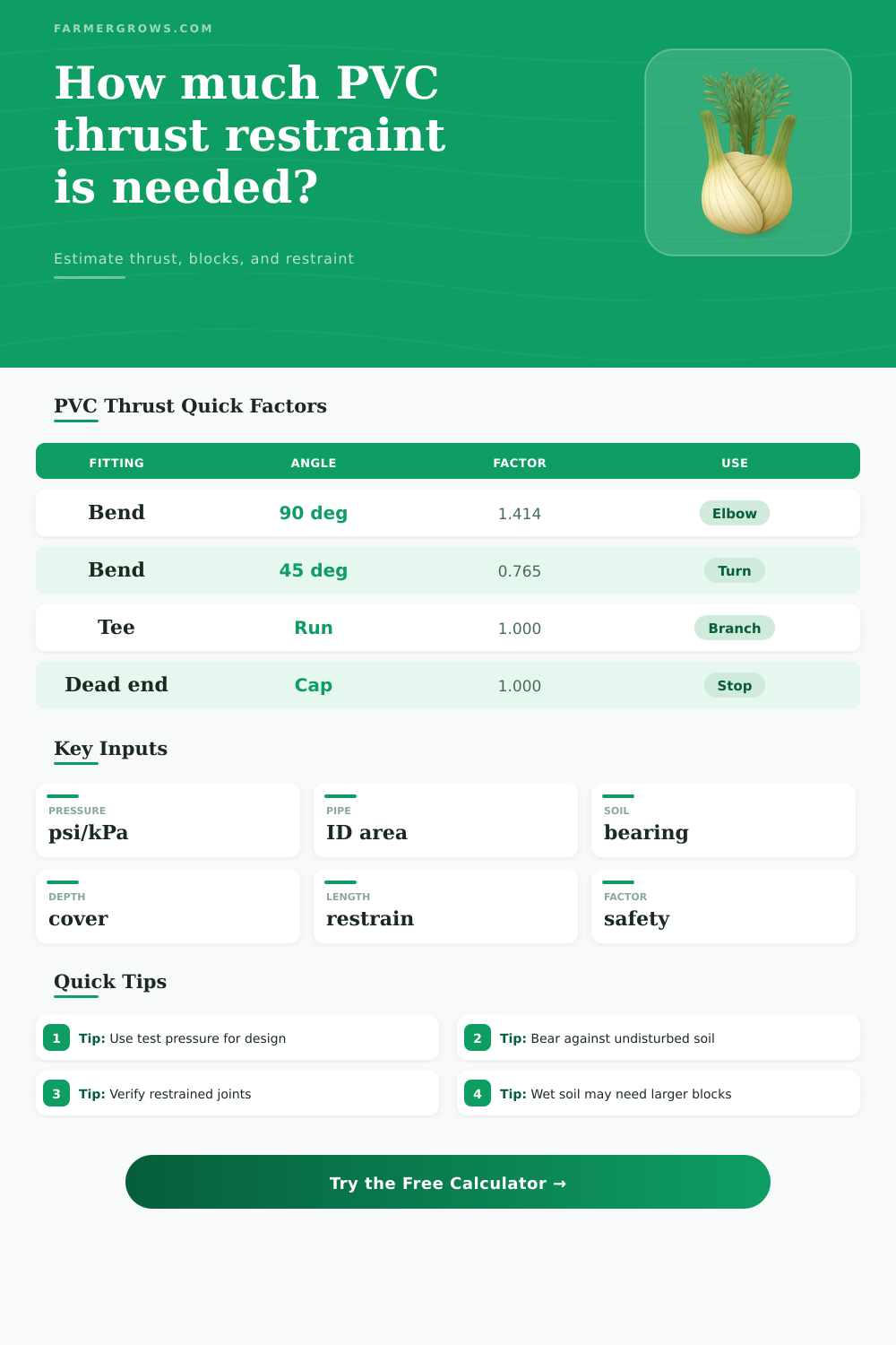
Thrust Coefficients by Fitting
| Fitting | Formula used | Coefficient times PA | Notes |
|---|---|---|---|
| 90° bend | 2PA sin(90/2) | 1.414 | Large change in direction; usually controls block size. |
| 45° bend | 2PA sin(45/2) | 0.765 | About 54 percent of a 90° bend at the same pressure and diameter. |
| 22.5° bend | 2PA sin(22.5/2) | 0.390 | Often handled with smaller blocks or shorter restrained lengths. |
| 11.25° bend | 2PA sin(11.25/2) | 0.196 | Small deflection, but pressure surge can still matter. |
| Tee, plug, closed valve | PA | 1.000 | Used where pressure acts on the full pipe area. |
| Reducer estimate | P(A1 - A2) | 0.650 | This calculator uses a conservative first-pass area difference factor. |
Common PVC Internal Diameters Used
| Nominal PVC | Schedule 40 ID | Schedule 80 ID | Pressure area note |
|---|---|---|---|
| 2 in | 2.067 in | 1.939 in | Area is based on actual internal diameter, not nominal size. |
| 3 in | 3.068 in | 2.900 in | Higher schedule slightly lowers hydraulic area. |
| 4 in | 4.026 in | 3.826 in | A 4 in 90° bend at 150 psi produces about 2700 lb before safety factor. |
| 6 in | 6.065 in | 5.761 in | Thrust rises with the square of pipe ID. |
| 8 in | 7.981 in | 7.625 in | Large mains need careful bearing and joint restraint review. |
Soil Bearing Values for Preliminary Sizing
| Soil condition | Typical bearing | Metric equivalent | Use caution when |
|---|---|---|---|
| Soft clay, wet silt, loose fill | 750 to 1000 psf | 36 to 48 kPa | Trench wall smears, sloughs, or has standing water. |
| Firm clay or compacted loam | 1500 psf | 72 kPa | Soil is seasonally saturated or recently disturbed. |
| Sandy clay or compact sand | 2000 psf | 96 kPa | Pipe bedding was over-excavated near the fitting. |
| Dense sand, gravelly soil | 3000 psf | 144 kPa | Soil is uniform and the block bears on undisturbed wall. |
Restrained Joint Planning Ranges
| Joint or restraint type | Calculator capacity basis | Best application | Field check |
|---|---|---|---|
| Push-on gasket, block only | 60 lb per ft per inch | Short laterals with a proper concrete block. | Do not count ordinary gasket joints as locked restraint. |
| Solvent-welded PVC | 120 lb per ft per inch | Small farm and greenhouse pressure lines. | Confirm cure time before pressure testing. |
| Mechanical restrained joint | 220 lb per ft per inch | Buried PVC mains with listed restraint products. | Install torque and gasket details to manufacturer instructions. |
| Tie rods or clamps | 260 lb per ft per inch | Valves, tees, and fittings with accessible restraint hardware. | Protect hardware against corrosion and bending. |
| Fused or fully restrained pipe | 320 lb per ft per inch | Continuous restrained runs or specialty pipe systems. | Use published pullout and pressure ratings. |
Block bearing note: The required area is the face bearing against undisturbed trench wall in the direction opposite the thrust. Keep concrete clear of pipe joints and fittings that need service access.
Pressure note: Surge pressure can exceed normal pump pressure when valves close fast or pumps stop suddenly. Use the highest design or test pressure required for the line.
When you send pressurized water through a PVC pipe, the fittings moves due to the water pressure. The 90-degree bend will push outward due to the force of the water. The tee fitting will try to split apart at the branch.
The dead-end cap will act as a piston. If you dont check to see if these components will move in these ways, you risk the joints cracking due to such movements, shifting of the line due to such movements, or the line will blow apart during a pressure test. Thrust restraints will prevent these movements.
How to Stop PVC Pipe Joints from Moving
A calculator is a tool that will help you to determine the size of the restraints by calculating the parameters of the line. The force of the water is a measurement of the pressure applied to the internal area of the PVC pipe. The geometry of the fitting will decide how much of that force is applied to the joint.
A straight reducer will experience the difference in area between the two size of PVC pipe. However, the bend will multiply the force apply to the joint due to the angle of the bend. You will not have to remember the formula for the sine of the angle because the calculator for thrust restraints will provide that information when you enter the parameters for your pipe and joints of choice.
The output of the calculator is only an estimate of the force that the joints of your PVC piping system will experience. The output of the calculator will indicate whether the force of the water is small enough to use only small concrete blocks to provide the necessary thrust restraints for your PVC pipe joints, or whether the force is large enough to require a change in the type of joints of your PVC pipe system or the depth of covering in which the pipe will be buried. The bearing capacity of the soil in which your PVC pipe will be buried is another factor in the size of the concrete block that you will have to use to provide the necessary restraints for the joints of your PVC pipe system.
Large amounts of thrust force will require a large amount of thrust restraints from a concrete block if the soil in which the PVC pipe is buried is soft clay or disturbed fill. You can adjust the value of the soil parameter in the calculator so that you can input a value for wet soil or a higher value for dense sand. The value of the bearing strength of the soil will have the most impact on the size of the required bearing area for your PVC pipe joints.
If the bearing area that is required for your system is too large to provide with a single concrete block, you could increase the depth at which the PVC pipe is to be buried so that the passive soil strength will provide some of the necessary restraints for the joints, or you may change to a mechanical restrained joint or fused system so that less area is required for bearing, or you can excavate a trench that is wider in relation to the diameter of the PVC pipe so that you can pour a larger amount of concrete into the trench. The depth to which the PVC pipe will be buried has two impacts upon your joint system for PVC pipes. First, the deeper you bury the PVC pipe, the more the weight of the soil above the PVC pipe will contribute to counteracting any uplift forces that may act against the joints of the PVC pipe.
Second, the deeper the PVC pipe is buried, the more likely it will encounter firmer soil which will have a higher bearing value for the joints of the PVC pipe system. The calculator for determining the size of the thrust restraints for your PVC pipe system will account for both of these factors. However, digging deeper into the ground than the depth that the thrust restraint calculator calculated will cost more money and take more labor to dig; thus, the depth value is another parameter in which you will have to use your judgment to decide which value will best suit the restraints that the joints of the PVC pipe will experience.
The types of joints that you will utilize in your PVC pipe system will also impact the thrust force of your system. For instance, push-on gasket joints will not provide any thrust force of their own, meaning that the rest of the system must handle all of the thrust force of the water that is to pass through the PVC pipe system. Solvent-weld joints will contribute to the ability to manage some of the thrust force, but not enough to fully handle the forces of a high pressure test of the PVC pipe system.
However, mechanical restrained joints and fused system joints will shift some of the thrust force to the pipe system itself, reducing the amount of thrust force that is required of the concrete bearing blocks that are placed alongside the PVC pipe system. Thus, if you choose any of these joint types, the thrust restraints calculator will calculate a different length of PVC pipe for which the restraints are required. In either case, however, it is up to the designer of the PVC pipe system to ensure that the length of the system that the thrust restraints calculator calculates is enough to handle all of the thrust force that will act upon the system; if not, more restrained PVC pipe of the same system can be added to the system.
Many project installations will differ from the calculations made with the calculator. For example, you may have to excavate the trench in which the PVC pipe is to be buried beyond the depth and width of the trench that the calculator calculates; the wetness of the backfill in which the PVC pipe will be buried may be beyond the wetness of the soil that is measured when testing the site; and the pressure test that you will perform on the newly-installed PVC pipe system may be higher than the normal operating pressure for that PVC pipe system. Thus, the calculator cannot account for these variables.
However, it is recommended that you walk the PVC pipe system after you have poured the concrete block for the joints and before you begin to backfill the trench to ensure that the concrete is bearing against the soil that has not been disturbed during the installation of the PVC pipe system. If the concrete is not bearing against the undisturbed soil, then the calculations that were made with the calculator are not going to be of any use to you. Many people make mistakes when calculating the thrust force that the joints of the PVC pipe system will experience.
For example, one of the most common mistakes is to use the nominal size of the PVC pipe for the area of the PVC pipe; the difference between these two sizes is small for 2-inch PVC pipe; but the difference between the two sizes of PVC pipe becomes more pronounced as the size of the pipe increases. In addition to this error, a second very common mistake is to not consider the safety factor for the pipe system. For instance, a safety factor of 1.5 is common and recommended; however, other codes may require the use of a safety factor of 2.0 if the PVC pipe system is to be used for critical applications or if there is likely to be a surge in the pressure of the water that pass through the PVC pipe system.
You can easily adjust this safety factor in the calculator for determining the size of the thrust restraints. When you determine that the result of the calculator is an acceptable result, it is still recommended that that result is compared to the tables that list the parameters of the joints that are manufactured by the company that manufactures the PVC pipe system. These tables include factors such as the testing loads that were applied to the joints and how those tests resulted in some of the strengths of the joints to be reduced when compared to their maximum strength.
Therefore, although the thrust restraints calculator can provide a very useful calculation of the size of the thrust restraints that are required for the PVC pipe system that you are to build, it is still recommended that you review the manufacturer’s tables to ensure that the restraints that are calculated with the calculator will be adequate for the joints that are to be used in the PVC pipe system. Thus, using both the calculator and the manufacturer’s tables will provide a more thorough and complete determination of the thrust restraints that are to be applied to the PVC pipe system. However, it is also important to understand that the calculator cannot replace your knowledge of the different types of PVC joints that are available in the market; by understanding each of the joints’ capabilities and limitations, you will be able to design a system that ensures that both the number and the conditions of the location in which the pipe is to be installed will result in the successful installation of the PVC pipe system.