Booster Pump Sizing Calculator
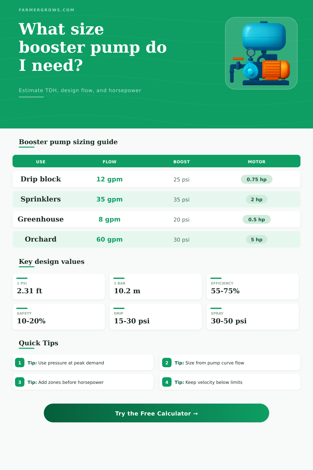
Estimate the pressure rise, total dynamic head, total zone flow, brake horsepower, and rounded motor size for a farm, greenhouse, or yard irrigation booster pump.
Choose a realistic irrigation case to load the calculator. Each preset sets target flow, pressure rise, elevation lift, pipe loss, fitting loss, zones, efficiency, and margin.
✅ Booster Pump Sizing Results
Results update from your irrigation demand and pressure inputs.
Good for moderate boost and clean water. Usually economical when TDH is modest and the flow is steady.
Best fit when pressure rise is high, space is limited, and drip or spray zones need stable pressure.
Useful for small farm systems with lower flow demand. Check priming limits and noise before choosing.
Works well from tanks or wells when flooding the suction side improves priming and cooling.
Helpful for multiple zones because speed control can hold pressure as zones open and close.
Drip needs pressure stability, sprinklers need both pressure and flow, and filters add loss as they load.
| Pressure Increase | Head in Feet | Head in Meters | Common Use |
|---|---|---|---|
| 10 psi / 0.69 bar | 23.1 ft | 7.0 m | Light drip correction |
| 20 psi / 1.38 bar | 46.2 ft | 14.1 m | Drip or greenhouse zones |
| 30 psi / 2.07 bar | 69.3 ft | 21.1 m | Spray heads and filters |
| 40 psi / 2.76 bar | 92.4 ft | 28.2 m | Higher pressure sprinkler work |
| 50 psi / 3.45 bar | 115.5 ft | 35.2 m | Washdown or long runs |
| Irrigation Type | Typical Outlet Pressure | Typical Zone Flow | Sizing Note |
|---|---|---|---|
| Drip tape block | 8-15 psi | 4-20 gpm | Regulate after filtration |
| Orchard drip | 15-30 psi | 15-80 gpm | Account for long laterals |
| Greenhouse benches | 20-35 psi | 3-15 gpm | Uniformity matters more than peak psi |
| Spray heads | 30-50 psi | 15-60 gpm | Check nozzle chart at design pressure |
| Impact sprinklers | 40-70 psi | 20-120 gpm | Need pump curve flow at high head |
| Washdown hose | 45-75 psi | 8-30 gpm | Short duty can tolerate cycling |
| Total Flow | 75 ft TDH | 125 ft TDH | 175 ft TDH |
|---|---|---|---|
| 10 gpm | 0.29 hp | 0.49 hp | 0.68 hp |
| 25 gpm | 0.73 hp | 1.21 hp | 1.70 hp |
| 50 gpm | 1.46 hp | 2.43 hp | 3.40 hp |
| 75 gpm | 2.18 hp | 3.64 hp | 5.10 hp |
| 100 gpm | 2.91 hp | 4.86 hp | 6.80 hp |
| Check | What to Compare | Good Sign | Warning Sign |
|---|---|---|---|
| Flow point | Total design flow | Curve passes through demand | Pump cannot reach flow |
| Head point | Design TDH after margin | Point sits near efficient range | Point is near shutoff head |
| Efficiency | Pump curve efficiency island | Operating point near peak | Oversized pump throttled hard |
| NPSH | Suction pressure and elevation | Available NPSH exceeds required | Noise, cavitation, or air draw |
| Controls | Zones and pressure switch range | Stable pressure at each zone count | Rapid cycling or pressure swings |
When choosing a booster pump for an irrigation system, it is necessary to match the pressure and flow requirements of the plants to the capability of the booster pump. Many individuals wants to choose a booster pump based on the size of the motor for the booster pump. However, choosing a booster pump based only on the size of the motor for the booster pump can lead to error.
The real conditions for the system need to be accounted for when choosing a booster pump. The pressure boost created by the booster pump is the difference in pressure between the inlet of the booster pump and the outlet of the booster pump. This difference in pressure will create head for the system.
How to Choose the Right Booster Pump for Your Irrigation System
The pressure, lift, and friction losses for the system will all be additive component of the total dynamic head. The elevation of the field relative to the booster pump will add resistance to the flow of water to the system. This resistance occurs whether the booster pump need to push water to the field or water must be drawn from a tank located below the field.
The friction losses for the system will increase with the flow rate of water and the distance that the water must travel through the system. Additionally, the friction losses will increase with the number of fittings, valves, and filter included in the system. The design flow of the system will be the flow rate required to water a single zone in the irrigation system multiplied by the number of irrigation zone in the system.
If the designer of the irrigation system chooses a booster pump that is sized only to supply one irrigation zone but the irrigator later decide to run two irrigation zone at the same time, the pressure at those zones will drop. This will make it impossible for the irrigation system to provide uniform coverage of each zone in the irrigation system. Therefore, the designer of the irrigation system must calculate the flow rate of water based on the number of irrigation zone that will run simultaneously.
Following determining the design flow of the system, the total dynamic head of the system can be calculated. With these two values, the brake horsepower of the system can be calculated using the water horsepower formula. Because the efficiency of the booster pump will never reach 100 percent, the motor for the booster pump will need to be larger than calculated.
A safety margin must also be added to the size of the motor. The safety margin will account for any additional resistance that is created by aging filter or seasonal debris that might collect in the system. For irrigation systems, the operating point of the system must be matched to the published curve for the manufacturer of the booster pump.
The operating point for the system that is closest to the best-efficiency island on the curve for the booster pump will use less electricity to operate the irrigation system. Furthermore, the life of the booster pump will be longer when the system operate at this point rather than if the manufacturer selects an oversized booster pump for the system. Single-stage centrifugal booster pumps are typically used for irrigation systems with moderate pressure requirement.
However, multistage booster pumps are used when the irrigation system requires higher pressure than can be supplied by a single-stage centrifugalpump. Additionally, jet pumps can be used for irrigation systems with smaller requirements for flow rate of water. However, care must be taken to ensure that the limits for priming the jet pump are not exceeded.
Another type of booster pump that can be used is a submersible booster pump. Because the submersible booster pump is submerged in the water to be moved, the submersible booster pump typically will run cooler than single-stage centrifugalpumps or multistage booster pumps. These types of booster pumps can be challenging to install in an existing system, though.
However, using a variable-frequency drive for the motor will allow for better control of the water pressure in the irrigation system. Furthermore, the variable-frequency drive will keep the irrigation system’s pressure steady when some of the irrigation zones open and others close. Irrigation systems will rarely operate in ideal conditions.
The inlet water pressure for an irrigation zone will drop if the water supply well for that system takes time to recover its water level. Additionally, the inlet water pressure will drop if the filter in the irrigation system becomes loaded with debris from the field to be irrigated. The water pressure at various points along the lateral irrigation pipe may not be equal due to changes in elevation.
This uneven water pressure cannot be corrected downstream from the irrigation zone with emitter or nozzle control. The density of the water can change with the water temperature. Changes to water density will change the head that the booster pump must move.
However, changes to the water temperature will likely be small for irrigation systems. The cycle of operation for the booster pump will likely not be continuous. Pumps that are only used a few hours per day will allow the manufacturer to use a point on the performance curve of the booster pump with lower efficiency than a system that is required to operate continuously.
Common error when sizing a booster pump are using only the static water pressure for the irrigation system as the important number for irrigation system sizing. The static pressure for an irrigation system will be sufficient when no water is flowing to the zone but will drop to the dynamic pressure needed by the irrigation zones when the largest irrigation zone is opened. Another common error when sizing a booster pump is sizing the system based on the horsepower of the motor for the pump before determining the flow and head of the irrigation system.
If the designer of the system sizes the irrigation system for the horsepower of the motor for the booster pump first, the booster pump may not reach the necessary pressure for the irrigation system or could be running at a point on its performance curve for which it is not efficient in moving water. The suction piping for an irrigation system should not be undersized. If the suction piping is undersized, cavitation form in the system.
Pumps with cavitation will experience damage to their seal. The discharge piping for an irrigation system cannot be undersized. Although oversized discharge piping for an irrigation system will cost more money for the irrigator to purchase and install, the oversized discharge piping will not hurt the performance of the irrigation system.
The table provided in this calculator will provide context for the calculations performed for the irrigation system. The conversions of pressure to head can help the designer of the irrigation system to compare the head of a drip irrigation system to that of a sprinkler irrigation system. The tables can include examples of the target irrigation types and how they will require different pressure and flow rate at each zone in an irrigation system.
The horsepower example can tell the designer of an irrigation system how many horsepower the irrigation system will require. The information will help the designer decide if a 2-horsepower motor for the booster pump will be adequate for the design of that irrigation system. After calculating the total dynamic head and the brake horsepower for the irrigation system, a booster pump can be found whose performance curve passes through the calculated point for the system.
The net positive suction head must also be checked and ensure to be greater than the requirement for the booster pump. The motor for the booster pump should also have a service factor that allows for the additional load on the motor during hot weather or dirty filter. The pressure switches, irrigation tanks, and variable-frequency drives for the booster pump should also be set appropriately so that the booster pump does not short cycle when only one small irrigation zone requires watering.
By following these steps when installing a booster pump for an irrigation system, the booster pump will deliver sufficient pressure to each emitter or nozzle in the system. Furthermore, each component of the irrigation system will operate within its designed parameter so that water and energy will not be wasted, and the motor will not be damaged.