🌬 Wind Turbine Cable Size Calculator
Estimate wind turbine cable AWG from turbine watts, DC or AC voltage, one-way run length, inverter distance, conductor material, voltage drop target, parallel runs, and temperature derating.
Recommended Wind Turbine Cable Estimate
The selected AWG is the smallest size that meets voltage drop and temperature-adjusted ampacity for the entered current, distance, material, and parallel runs.
| Size | Circular mils | Copper amps | Aluminum amps |
|---|---|---|---|
| #14 | 4,110 | 20 A | - |
| #12 | 6,530 | 25 A | 20 A |
| #10 | 10,380 | 35 A | 30 A |
| #8 | 16,510 | 50 A | 40 A |
| #6 | 26,240 | 65 A | 50 A |
| #4 | 41,740 | 85 A | 65 A |
| #2 | 66,360 | 115 A | 90 A |
| 1/0 | 105,600 | 150 A | 120 A |
| 2/0 | 133,100 | 175 A | 135 A |
| 4/0 | 211,600 | 230 A | 180 A |
| Turbine output | 24 V current | 48 V current | 240 V current |
|---|---|---|---|
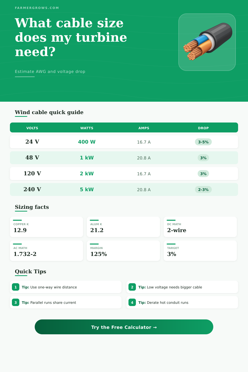
| 400 W | 16.7 A | 8.3 A | 1.7 A |
| 800 W | 33.3 A | 16.7 A | 3.3 A |
| 1,500 W | 62.5 A | 31.3 A | 6.3 A |
| 3,000 W | 125 A | 62.5 A | 12.5 A |
| 5,000 W | 208 A | 104 A | 20.8 A |
| Cable segment | Common target | Why it matters | Planning note |
|---|---|---|---|
| Battery DC cable | 1% to 2% | High current at low voltage | Short and large conductors |
| Turbine to controller | 2% to 3% | Protect charging harvest | Use true one-way path |
| Controller to inverter | 1% to 3% | Inverter surge can be high | Check inverter manual |
| AC output feeder | 3% to 5% | Higher voltage carries fewer amps | Check code and load type |
| Long farm trench | 3% to 5% | Material cost rises quickly | Compare aluminum and copper |
| Location condition | Approx temp | Factor | Effect |
|---|---|---|---|
| Cool battery room | 86 F / 30 C | 1.00x | Base ampacity |
| Warm equipment shed | 95 F / 35 C | 0.94x | Small derate |
| Sun-exposed conduit | 104 F / 40 C | 0.88x | Moderate derate |
| Hot roof raceway | 113 F / 45 C | 0.82x | Upsize likely |
| Very hot enclosure | 122 F / 50 C | 0.75x | Heavy derate |
For wind systems, low voltage is the cable-size trap. A 1,000 watt turbine at 24 V moves twice the current of the same turbine at 48 V, so voltage drop climbs quickly.
Measure the one-way physical path, then include the inverter distance only when the same current actually flows through that cable segment.
Wind turbines produce the electricity that must travel through wires to a controller or an inverter. The size of the wire that is used to carry the electricity from the turbine to the controller or inverter impact how much energy is lost during the transmission of that energy. Using a wire that is too small for the amount of energy that the turbine produces will produce heat within the wire, the wire will reduce the charging rate of the battery bank, and the turbine may cause circuit breakers to trip during periods of high wind.
In order to avoid these problems, you must select the correct size wire for the system. In order to calculate the correct size wire, you must first calculate the current that the turbine produces. You can calculate the current by dividing the wattage of the turbine by the voltage of the system.
How to Choose the Right Wire Size for Wind Turbines
Turbines with the same wattage will produce more current at a lower voltage than those with a higher system voltage. Therefore, the 24 volt turbine will require a thicker gauge wire than the 48 volt turbine with the same power output. In order to calculate the correct wire size, you should use the actual current that the turbine produces rather than the wattage of the turbine.
As the electricity travels through the wire, the voltage of the system will drop. You can calculate the voltage drop that is created within the wire by dividing the voltage of the system by the voltage of the wire. Most systems will require a voltage drop of no more than 2 to 3 percent.
If the voltage drop is higher than 3 percent, the charging current of the system will drop. The voltage drop is dependent upon both the length of the wire as well as the voltage of the system. The longer the wire and the lower the voltage of the system, the more higher the voltage drop of the system.
The material that is used for the wire is another important factor in the electrical system. Both copper and aluminum wires has different levels of resistance in the wires. Copper has a lower resistance than aluminum wires.
This means that copper wires can carry the same amount of current as aluminum wires yet have a smaller diameter. Aluminum wires are less expensive than copper wires yet require a larger diameter to allow for the same amount of current to pass through the wire as copper wires. A copper and aluminum wire comparison calculator can be used to determine the current carrying capacity of both types of materials.
In order to calculate the voltage drop of the wire, you must measure the distance that the wire will travel in one direction from the turbine to the battery or inverter. You should not measure the round trip distance of the wire from the turbine to the battery inverter as this will make the wire distance longer than it should be. If measuring the distance for an inverter segment the wire distance should only be measured from the turbine to the inverter if the current of both segments of the wire is the same.
The voltage drop is cumulative thus any distance measurement calculators will account for this in the recommended wire length. In addition to measuring the distance of the wire, the wire can be run in parallel with another wire segment. Using two wires instead of one will allow the system to carry twice the amperage of one wire.
Additionally, using two wires in parallel will reduce the voltage drop of the wire segment by half. This option is used for situations in which it is difficult to pull a single large wire through a conduit. An additional factor to consider when using wire segments in parallel is the temperature of the wire.
The higher the temperature of the wire, the less amount of current can travel through the wire. In situations in which the wire will be exposed to higher temperatures, the wire ampacity calculator will account for this and recommend a larger diameter wire to reduce the chance of overheating of the wire. In addition to accounting for the voltage drop in the system, it is important to include a margin of safety into the electrical system calculations.
Adding a 125 percent margin to the current calculations means that the wire will be able to handle 25 percent more current than the systems current requirements. This is important for wind turbine systems since the wind gusts may create a surge in the power output of the turbine. Once the calculations have been performed with the wire ampacity calculator, a comparison grid of wire sizes can be used to determine the best size wire for the system.
Using a comparison grid will allow individuals to determine if the smaller gauge wire will fail the voltage drop requirements. The larger gauge wire will allow for more flexibility in the case that more turbines is to be installed in the future. In some cases, the comparison grid will offer options for using wires in parallel to reduce the difficulty of installing the wire into the system.
In addition to the calculations that are performed with the wire ampacity calculator, there are some common mistakes with wire sizing for wind turbine systems. One of the most common mistakes is measuring the round trip distance for the wire rather than the distance from the turbine to the battery or inverter. Another mistake is to ignore the length of the wire that connects to the inverter if the current of that segment of wire is the same as the turbine segment.
Using the wire ampacity calculator ignores voltage drop if only considering the ampacity of the wire. Finally, another mistake is to assume that the turbine will always experience the rated voltage as the voltage of the system will drop if the wind speeds are low. An understanding of these mistakes will allow individuals to create an accurate electrical system in which the wire is large enough to avoid the loss of energy from the turbine.