Rainwater Outlet Calculator
Size roof drainage outlets, throat diameter, drain count, and storm pipe capacity from roof area, rainfall intensity, runoff coefficient, head depth, and pipe slope.
Use this calculator for farm roof drainage planning on barns, sheds, greenhouses, and rainwater collection inlets. Confirm final sizing with local rainfall maps, plumbing code, overflow requirements, and a qualified designer for occupied or high-risk structures.
Rainwater Outlet Sizing Results
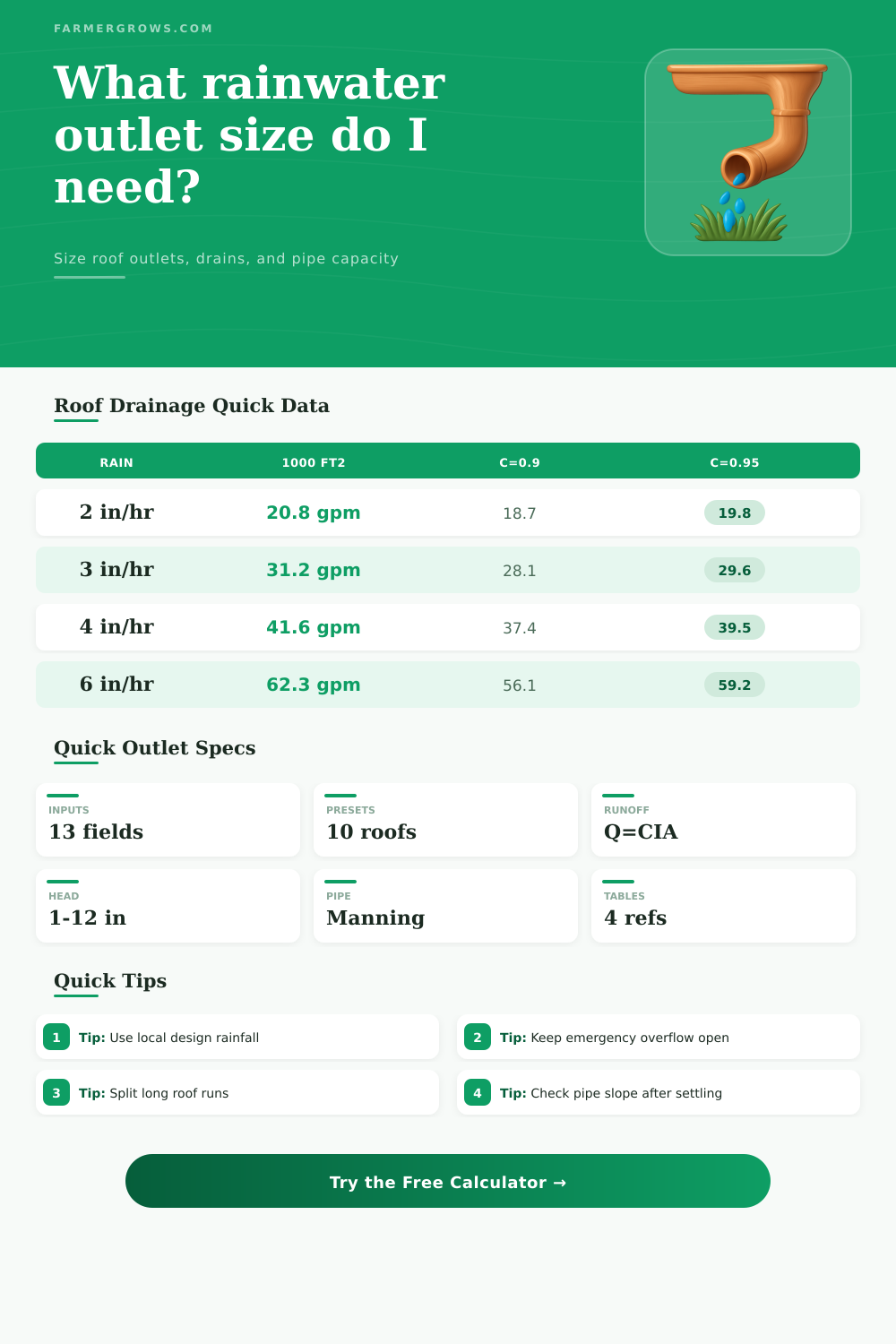
| Design rain intensity | Flow per 1,000 ft² | Metal roof C 0.95 | Membrane roof C 0.90 | Green roof C 0.50 |
|---|---|---|---|---|
| 1 in/hr | 10.4 gpm before coefficient | 9.9 gpm | 9.4 gpm | 5.2 gpm |
| 2 in/hr | 20.8 gpm before coefficient | 19.7 gpm | 18.7 gpm | 10.4 gpm |
| 3 in/hr | 31.2 gpm before coefficient | 29.6 gpm | 28.1 gpm | 15.6 gpm |
| 4 in/hr | 41.6 gpm before coefficient | 39.5 gpm | 37.4 gpm | 20.8 gpm |
| 6 in/hr | 62.3 gpm before coefficient | 59.2 gpm | 56.1 gpm | 31.2 gpm |
| Roof surface | Runoff coefficient | Use in calculator | Field note |
|---|---|---|---|
| Metal panel roof | 0.95 | Most barns, shops, machine sheds | Fast runoff; valleys and snow guards can concentrate flow |
| Greenhouse plastic or glass | 0.92 | High tunnels, glass houses, propagation roofs | Keep film edges and gutter lips clear of leaf debris |
| Single-ply membrane | 0.90 | Flat farm shop or packing building | Primary and overflow drains should both stay open |
| Asphalt shingle roof | 0.85 | Farm office, cooler, small outbuilding | Slightly more storage and wetting than metal panels |
| Gravel-ballasted roof | 0.80 | Older low-slope utility roofs | Check strainers often after wind and leaf events |
| Extensive green roof | 0.50 | Vegetated roof with growing medium | Coefficient varies with soil depth and saturation |
| Round outlet throat | 2 in head, Cd 0.62 | 4 in head, Cd 0.62 | 6 in head, Cd 0.62 | 8 in head, Cd 0.62 |
|---|---|---|---|---|
| 2 in throat | 19 gpm | 27 gpm | 33 gpm | 39 gpm |
| 3 in throat | 44 gpm | 62 gpm | 76 gpm | 88 gpm |
| 4 in throat | 78 gpm | 110 gpm | 135 gpm | 156 gpm |
| 6 in throat | 175 gpm | 248 gpm | 304 gpm | 351 gpm |
| 8 in throat | 312 gpm | 441 gpm | 541 gpm | 624 gpm |
| Smooth PVC pipe | Capacity at 1% slope | Capacity at 2% slope | Capacity at 4% slope | Practical roof drainage use |
|---|---|---|---|---|
| 2 in full pipe | 23 gpm | 33 gpm | 46 gpm | Small lean-to or tank inlet tailpiece |
| 3 in full pipe | 80 gpm | 113 gpm | 160 gpm | Small shed outlet or short collector |
| 4 in full pipe | 181 gpm | 256 gpm | 362 gpm | Common barn roof drain conductor |
| 6 in full pipe | 624 gpm | 883 gpm | 1,249 gpm | Large roof collector or buried storm line |
| 8 in full pipe | 1,488 gpm | 2,104 gpm | 2,976 gpm | Main line for multiple roof outlets |
Before choosing the outlet: Size the primary drain for the design rainfall, then provide a separate overflow path where a blocked basket cannot add unsafe roof load.
Before trenching pipe: Recheck the actual slope after settlement, include cleanouts at bends, and avoid routing roof water toward manure, feed, or equipment storage areas.
Rainwater drainage on a farm roof require careful planning to avoid pooling of water on the roof that may result from improper drainage. Pooling water can result in roof overflow and outlet blocking, which can lead to the development of a pond on the roof. The movement of water across the roof must be determined to ensure the drains and pipes to which the roof will be installed has the appropriate size to avoid placing the roof in danger if incorrect sizes are selected for those drains or pipes.
The type of material of the roof will factor into the planning of the roofs drainage system. Different types of roofing materials will result in different amount of water becoming runoff from that roof. For instance, a metal panel roof will allow the rainwater to shed almost immediately from that roof, while gravel ballasted and green roofs will hold back some of the water that lands on those roofs.
How to Plan Rainwater Drainage on a Farm Roof
The designer should select the coefficient for these different types of materials for the specific roof that will be built, as either underestimating or overestimating the drainage capabilities of the roof can lead to complication in the drainage system. The depth of the water head above the outlet that will be installed on the roof will factor into the planning of that drainage system. The standing water will create a flow of water through the diameter of the outlet, but will also add to the weight of that roof structure.
Calculators can help to determine the different depths of water head that can be installed on the roof and how much additional drainage system capacity that each additional depth of standing water will create; this information can assist in the decision of how deep the roof drains should be built prior to the additional weight of water becomes too much for the roof structure. The slope of the downstream portion of the roof, the diameter of that pipe, and the roughness of the material of that pipe will create the capacity of the downstream pipe. Even if the downstream pipe appear to have the capacity to allow for the amount of water from the roof to pass through it, the downstream pipe may fall short due to these factors.
Use of the Manning equation will help determine if the downstream pipe has enough capacity to allow the majority of the water from the roof to pass through to it’s destination. Another factor to consider is the length of the roof. Rainwater has to travel the length of the gutter to the outlet.
If there is any bottlenecks created by the sagging of the gutter or the presence of debris in the gutter, the roof drains will have to be installed at intervals along that length of the gutter. Using a calculator to determine at what distances along the length of the gutter the drainage outlets should be installed can assist in the decision of whether the drains for the roof should be two larger drains or four smaller drains. Finally, emergency overflows will be necessary for the drains on the roof.
An emergency overflow will allow the water to find an alternate path over the roof if the main drains become blocked by debris. The designer can build the emergency overflows slightly higher than the main drainage outlets to allow for the escape of water if the main drains become blocked by ice or leaves. Drainage systems for farms must include an emergency overflow to accommodate the types of items that may be on the roof.
All of the factors mentioned above are based off the local rainfall data. The rainfall data for the location will determine the intensity that the rainwater will have. Using the rainfall data for another location could result in an undersized or oversized drainage system.
By adjusting one variable within the calculation of the drainage system components, it is possible to determine the effect that each factor has upon the others; this information will allow the farmer to make decisions regarding the various components of their drainage system.