Pump Head Calculator
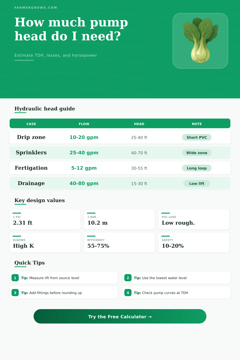
Estimate total dynamic head from lift, pressure, straight-pipe friction, and fitting losses. The result helps you size a pump that still performs at the real system load.
Pick a realistic farm or yard case to seed the calculator. Each preset loads a flow rate, lift, suction condition, pressure target, piping, fittings, fluid, and efficiency.
Method: Darcy-Weisbach friction with Haaland friction factor, plus static lift, suction lift, discharge pressure, and a safety margin.
Pump head snapshot
Enter values to calculate total dynamic head.
| Material | Roughness | Relative | Use |
|---|---|---|---|
| PVC | 0.0015 mm | Very smooth | Low friction runs |
| HDPE | 0.0015 mm | Smooth | Flexible farm line |
| Copper | 0.0015 mm | Smooth | Clean water loops |
| Steel | 0.045 mm | Moderate | General service |
| Fitting | K each | 2 in eq | Comment |
|---|---|---|---|
| Sweep elbow | 0.35 | 1.5 m | Gentle turn |
| Std elbow | 0.75 | 3.2 m | Common bend |
| Gate valve | 0.17 | 0.7 m | Full open |
| Tee branch | 1.50 | 6.5 m | Side takeoff |
| Pressure | Head | Formula | Note |
|---|---|---|---|
| 1 psi | 2.31 ft | psi x 2.31 | Water at 20 °C |
| 1 bar | 33.9 ft | bar x 33.9 | Metric quick check |
| 10 kPa | 1.02 m | kPa x 0.102 | Light pressure |
| 1 m | 1.42 psi | m x 1.42 | Water column |
| Scenario | Flow | Static | TDH |
|---|---|---|---|
| Drip zone | 15 gpm | 18 ft | 32 ft |
| Sprinkler | 30 gpm | 28 ft | 58 ft |
| Transfer | 60 gpm | 12 ft | 24 ft |
| Lift pump | 45 gpm | 35 ft | 64 ft |
Best when the pump curve crosses the TDH target near its efficient middle.
Useful when filters load up, hoses age, or the line gets a few extra elbows.
Trim flow while keeping headroom if seasonal demand changes through the year.
Strong option when uptime matters and one pump needs to cover the other.
This pump head calculator combines lift, pressure, friction, and fittings into one practical TDH value so you can choose a pump that stays effective under real field conditions.
When designing an irrigation system, it is essential to understand teh concept of head. Head is the total amount of energy that the water require to get from one place to another. Head is not just the vertical distance between the water source and the irrigation system.
Head is also a measurement of the energy that is required to overcome the various form of resistance that exist within the system. If resistance is not accounted for in the design of the irrigation system, the pump will either not have enough pressure to push the water through the system or will be required to work under too much load for the systems requirements. Head is comprised of a few different elements, all of which a designer must account for in the design of an irrigation system.
What Head Means in an Irrigation System
The first element of head is static head. Static head is the vertical distance that the water must travel upward from the water source to the irrigation system. For instance, if the water is to be moved from a low pond to a high hill, the vertical distance between those two locations is the static head of the system.
The static head represent the energy that is required to overcome gravity. Gravitational energy will always work against the irrigation systems pump, as it will always pull the water downwardly. Therefore, the pump will always need to work to provide enough energy to overcome gravitational pull.
The static head is not the only component of head, however. Another component of head is friction loss. Friction loss is the energy that is lost by the water as it rubs against the walls of the irrigation systems pipes.
The rougher the pipes, the more energy that the water will lose as it moves through the system. Smooth pipes will exhibit less friction loss than rough pipes. Another factor that contributes to friction loss is the diameter of the irrigation systems pipes.
The diameter of the irrigation systems pipes will have an impact on the amount of energy that is lost due to friction. If narrow pipes are used in the irrigation system, the water will have to move at a higher velocity to deliver the same amount of water through the system as compared to wider pipes. Higher velocities within the system will result in greater friction loss within the system.
Therefore, narrow pipes will result in greater friction loss than wide pipes. Many individuals that design irrigation systems may attempt to save money by using narrow pipes to reduce the cost of pumping that water. However, narrow pipes will result in increased friction loss for the system, which will require a more powerful pump to push the water through the system.
Besides the energy that is lost due to friction within the systems pipes, another consideration is the energy that is lost when the water change direction within the system. Such energy loss is referred to as minor losses. Any time the water changes the direction within the system, such as when it passes through a valve or makes a turn through an elbow, the water will lose a small amount of energy.
For instance, a ninety-degree elbow will cause more loss of energy than a sweep elbow. These losses of energy, along with static head and friction loss, combine to create the total dynamic head (TDH) of the system. The TDH is an important value for the designer to consider in the creation of the irrigation system.
TDH is the total amount of energy that is required to deliver the water to the various components of the irrigation system. Once the designer calculates the TDH for the system, it is important to consider the pump curve for the pump that is to be used within that irrigation system. The pump curve for a pump depicts the head that the pump can push with various flow rate of water.
Pumps are not designed to maintain a constant flow of water through the system. Therefore, it is important to ensure that the TDH of the system falls within the range of flow rates that are indicated on the pump curve. If the TDH is too close to the limits of the pump curve, even small changes within the system will drastically decrease the flow rates of water that can travel through the system.
For instance, if the filter for the system becomes clogged, the friction loss for the system will increase. An increase in friction loss will result in an increase in the TDH of the system. To account for this possibility, a designer should of build a safety margin into the calculation of the TDH of the system.
The last consideration for the designer is the power that is required to move the water through the system. The power that is required to push the water through the system is measured in units of brake horsepower. Brake horsepower is the amount of power that the motor must deliver to the pump shaft to overcome the TDH.
Another consideration for the designer is the efficiency of the pump. For instance, if the pump has low efficiency, most of the power that the motor provides will be lost as heat and vibration rather than being used to move the water. Therefore, if the pump has low efficiency, more power is required from the motor.
If all of these elements are consider and incorporated into the design of the irrigation system, the designer can calculate the TDH of the system and ensure that the pump that is selected will perform correctly for the system over a period of time.