Lateral Pipe Calculator
Size drip, tape, and micro-irrigation laterals with real Hazen-Williams friction, multiple emitters, slope head, inlet pressure, and flow conversion checks.
Use measured inside diameter when possible. The calculator treats each lateral as a pipe with evenly spaced outlets and applies a multiple-outlet factor, so friction is lower than a full-flow pipe over the same length.
Lateral Pipe Results
Flow is converted between gpm and lpm, friction is calculated with Hazen-Williams, and slope is added as elevation pressure change.
Calculation Breakdown
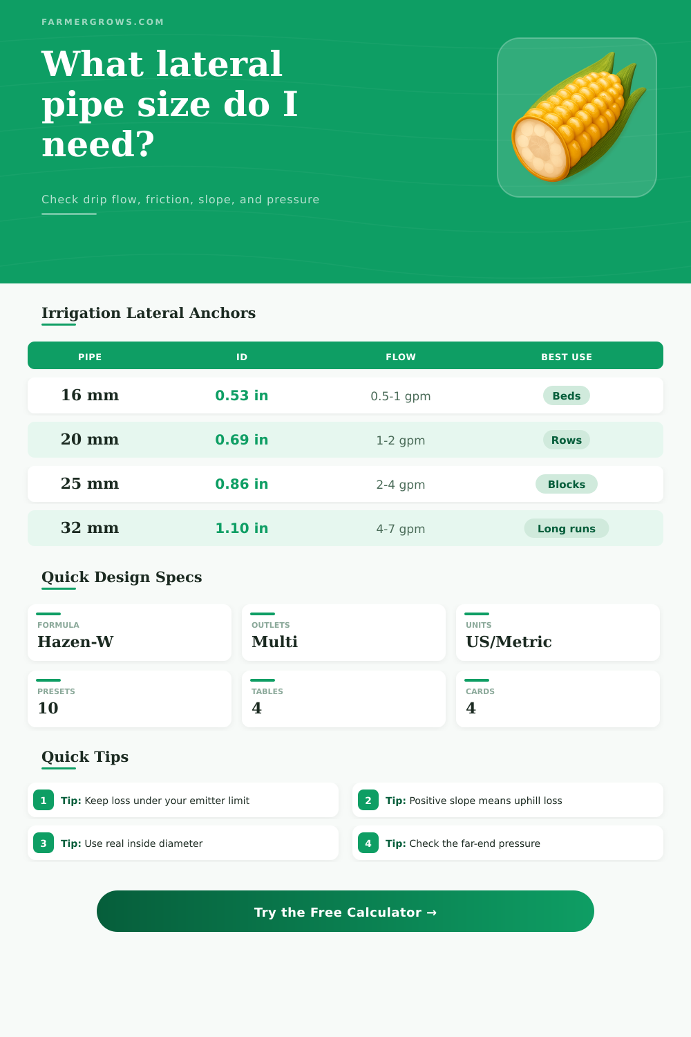
| Common pipe | Approx inside diameter | Typical lateral flow range | Practical use |
|---|---|---|---|
| 5/8 in drip tape | 0.55 to 0.62 in / 14 to 16 mm | 0.2 to 1.0 gpm / 0.8 to 3.8 lpm | Vegetable beds, annual crops, low seasonal pressure |
| 16 mm poly | 0.52 to 0.62 in / 13 to 16 mm | 0.4 to 1.5 gpm / 1.5 to 5.7 lpm | Garden rows, berries, compact tree rows |
| 20 mm poly | 0.65 to 0.72 in / 17 to 18 mm | 1.0 to 2.5 gpm / 3.8 to 9.5 lpm | Longer rows and moderate emitter spacing |
| 25 mm poly | 0.82 to 0.90 in / 21 to 23 mm | 2.0 to 4.5 gpm / 7.6 to 17.0 lpm | Micro-sprays, nursery lines, orchard laterals |
| 32 mm poly | 1.05 to 1.15 in / 27 to 29 mm | 4.0 to 7.5 gpm / 15.1 to 28.4 lpm | Heavy-flow blocks and long manifold-fed laterals |
Pipe labels vary by manufacturer and wall thickness. Enter measured inside diameter for the final friction check.
| Emitter pattern | Flow per emitter | Spacing | Where it fits |
|---|---|---|---|
| Low-flow tape | 0.16 to 0.25 gph / 0.6 to 0.9 L/h | 4 to 8 in / 10 to 20 cm | Greens, onions, shallow beds, sandy soil |
| Standard vegetable drip | 0.4 to 0.6 gph / 1.5 to 2.3 L/h | 8 to 12 in / 20 to 30 cm | Tomatoes, peppers, melons, mixed vegetables |
| Orchard button emitter | 0.5 to 1.0 gph / 1.9 to 3.8 L/h | 2 to 4 ft / 0.6 to 1.2 m | Young trees, shrubs, berries, vineyard rows |
| Micro-spray outlet | 5 to 15 gph / 19 to 57 L/h | 6 to 15 ft / 1.8 to 4.6 m | Nursery pots, orchard wetted circles, landscape beds |
| Pipe condition | Typical C factor | Friction effect | Use this when |
|---|---|---|---|
| New polyethylene or PVC | 145 to 155 | Lowest friction | Clean new plastic laterals and mainlines |
| Used plastic pipe | 135 to 145 | Slightly higher friction | Older lines with normal biofilm or mineral film |
| Aluminum irrigation pipe | 130 to 140 | Moderate friction | Portable systems with smooth interiors |
| Older steel or rough pipe | 100 to 120 | High friction | Rough, aged, or partly scaled pipe |
| Elevation change | Pressure change | Metric equivalent | Design note |
|---|---|---|---|
| 1 ft uphill | 0.43 psi loss | 1 m uphill = 9.8 kPa loss | Add this to friction loss from inlet to far end |
| 5 ft uphill | 2.17 psi loss | 2 m uphill = 19.6 kPa loss | Can exceed the friction budget on low-pressure drip |
| 5 ft downhill | 2.17 psi gain | 2 m downhill = 19.6 kPa gain | May over-water far-end emitters if unregulated |
| 10 ft change | 4.33 psi change | 3 m change = 29.4 kPa | Often needs pressure-compensating emitters or shorter runs |
Pressure tip: Compare the calculated far-end pressure with the emitter rating, not just the inlet pressure. A line can look fine at the valve and still under-feed the last plants.
Pipe tip: If the friction card is over the allowable loss, try a larger inside diameter first. Diameter has a strong effect in the Hazen-Williams equation.
When designing a drip irrigation system, you must consider the lateral pipe size to ensure that the water reaches each plant. The sizing of the lateral pipe is important because each foot of the lateral pipe, each emitter, and each change in the elevation of the pipe will change the water pressure that reach the crop. If the lateral pipe of the drip irrigation system has the wrong size, the water pressure at the end of the pipe might be too low for the drip emitters to function correct.
If the water pressure is too low, the plants at the end of the lateral pipe will recieve too little water. However, if the water pressure is too high at the beginning of the pipe, the plants at the beginning of the lateral pipe will receive too much water. You must choose the size of the lateral pipe so that the water pressure within the pipe is within the range of the requirements of the drip emitters.
Pick the Right Lateral Pipe Size for Drip Irrigation
Several factors will affect the water pressure within the lateral pipe, including friction, the slope of the lateral pipe, and the multiple-outlet effect. Friction will occur within the lateral pipe as the water move against the inside of the pipe. As the water moves along the lateral pipe away from the point of the inlet of the pipe, the water pressure will decrease due to friction.
The slope of the lateral pipe will also affect the water pressure within the pipe. If the land on which the drip irrigation system is established slopes in such a way that the elevation of the lateral pipe increases along its length, the water pressure within the pipe will decrease. In contrast, if the lateral pipe drops in elevation along its length, the water pressure within the pipe will increase.
The multiple-outlet effect is the result of water exiting the lateral pipe through each of the drip emitters. As water exits the lateral pipe through each emitter, the total amount of water moving through the lateral pipe decrease. Consequently, the friction acting on the lateral pipe also decreases along the length of the pipe.
The diameter of the lateral pipe is one of the critical factors to consider in calculating the friction that will act on the water moving through the pipe. The inside diameter of the pipe is the diameter of the lateral pipe that should be used in these calculations. Small change to the inside diameter of the lateral pipe will have a large effect upon the friction that acts on the water moving through the pipe.
You should measure the inside diameter of the lateral pipe. Many people tend to use the nominal or outside diameter of the lateral pipe in their calculations. These dimensions do not accuratly reflect the path of the water through the lateral pipe.
The pipe walls of lateral pipes can have varying thickness from manufacturer to manufacturer. Another factor that must be considered is the allowable pressure loss within the lateral pipe. The allowable pressure loss is the budget for the pressure within the lateral pipe.
The allowable pressure loss is the amount of pressure that is permitted for the water to lose between the inlet of the lateral pipe and the last emitter. If the allowable pressure loss within the lateral pipe is too small, the later sections of the pipe may not receive enough water to adequately irrigate the plants within those sections of the drip irrigation system. The type of emitter that are used within the drip irrigation system can change the allowable pressure loss.
Some of the emitters may be sensitive to changes in the water pressure moving through the lateral pipe. In such cases, the allowable pressure loss will have to be larger than the pressure loss that occur within other emitters that are not as sensitive to changes in the water pressure. If the allowable pressure loss is too small, then you can increase the diameter of the lateral pipe, shorten the length of the lateral pipe, or increase the inlet pressure of the lateral pipe.
The spacing between the emitters and the flow rate of the emitters will also impact the lateral pipe sizing of the drip irrigation system. The spacing between the emitters and the flow rate of the water will impact the friction within the lateral pipe. If the spacing between the emitters is smaller and each emitter has a lower flow rate than if the emitter spacing is larger and the flow rates of the emitters are higher, the friction within the lateral pipe will be different.
Both of these options are valid options for irrigating the plants, but the spacing of the emitters will impact the diameter of the lateral pipe that is use in the drip irrigation system. In addition to the factors mentioned above, there are also changes to the inside of the lateral pipe that will impact the sizing of the lateral pipe. For instance, over time, the lateral pipe may fill with mineral scale or biofilm that increases the roughness of the inside of the lateral pipe.
Increased roughness will increase the friction that acts on the water moving through the lateral pipe. Another factor to consider is the velocity of the water within the lateral pipe. High velocities of water will increase the friction within the lateral pipe.
High velocities within the lateral pipe may also move particle within the pipe that may lead to clogging of the lateral pipe. Low velocities within the lateral pipe may allow air pocket or sediment to remain within the lateral pipe. Air pockets and sediment within the lateral pipe will restrict the flow of water through the lateral pipe.
To avoid these problems, it is best to ensure that the velocity of the water within the lateral pipe is somewhere in the middle; it should be high enough to avoid the formation of air pockets or sediment within the pipe, yet it should be low enough to avoid high friction within the pipe. Many people make mistake when calculating the sizing of the lateral pipe for a drip irrigation system. One of the most common mistakes is to use the outside diameter of the lateral pipe rather than the inside diameter of the lateral pipe.
Another of the most common mistakes is to forget to account for the slope of the land on which the drip irrigation system is established. Another common mistake is to fail to ensure that the allowable pressure loss of the lateral pipe match the requirements of the drip emitters that are to be installed into the lateral pipe. By avoiding these mistakes, the drip irrigation system will distribute the water evenly to each plant within the planting area, and the drip irrigation system will function correctly throughout the growing season.