🚧 Inlet Control Culvert Calculator
Estimate runoff, compare allowable headwater, and size a round pipe or box culvert before you set the crossing.
This planner uses a runoff-based design flow and a full-flow Manning check. It is a practical first pass for farm lanes, ditch crossings, yard drains, and small road culverts.
Imperial uses feet, inches, and cfs. Metric uses meters, millimeters, and m3/s.
Size Summary
Runoff, selected culvert size, inlet capacity, barrel velocity, and cover check from the current inputs.
Calculation breakdown
| Diameter | Area | Full flow @1% | Typical use |
|---|---|---|---|
| 12 in | 0.79 sq ft | 1.8 cfs | Driveway edge |
| 18 in | 1.77 sq ft | 5.8 cfs | Farm lane ditch |
| 24 in | 3.14 sq ft | 13.8 cfs | Pasture swale |
| 36 in | 7.07 sq ft | 37.0 cfs | Road crossing |
Values above are quick planning guides. Inlet control can govern first, so check entrance type, headwater, and cover before finalizing.
| Surface | C | Storm response | Typical use |
|---|---|---|---|
| Roof | 0.90 | Fast | Outlets |
| Gravel | 0.40 | Moderate | Drive lanes |
| Pasture | 0.25 | Slower | Grass catchment |
| Pavement | 0.95 | Very fast | Aprons |
If the catchment mixes roof, gravel, and soil, choose the coefficient that best reflects the peak runoff path into the culvert.
Inlet control occur when the entrance of the culvert limits the amount of water that can pass through the culvert. The entrance to the culvert will act as a bottleneck that prevents the water from moving through the culvert in a desired way. As a result of this bottleneck, water will begin to pile up behind the culvert’s entrance.
The accumulation of this water will raise the levels of water that accumulate up to the culvert, or the headwater level. If the headwater level becomes too high, the water has the potential to spill over the bank or erode the soil in which the culvert is built. For many farm crossing that are shorter than 50 feet in length, inlet control is the main factor that regulate the capacity of the culvert to allow water to pass through.
What Is Inlet Control in Culverts
In order to prevent inlet control issues, a person will need to calculate the amount of runoff that will fall into the culvert during periods of precipitation. The amount of runoff that fall onto different types of surfaces will differ from one another. Each of these surface has a runoff coefficient that mathematically represents the amount of runoff that will occur from that type of surface.
For instance, fields of meadow grass have a low runoff coefficient of around 0.25, while rooftops have a high runoff coefficient of around 0.90. Additionally, gravel driveway will shed water faster than pastures covered in grass, indicating that the gravel driveway has a higher runoff coefficient than the pasture area. In order to calculate the amount of runoff that will enter the culvert, you will multiply the runoff coefficient of the area by the amount of rainfall and the size of the area that will be covered in runoff.
In addition to calculating the amount of runoff that will fall into the culvert, the result will be increased by a certain amount to provide for the excess water that may enter the culvert beyond the amount that was calculated. The slope of the land is another critical piece of information that must be gathered to ensure that inlet control does not occur within the culvert. The slope of the land will determine the velocity of the water that move through the culvert.
Should the slope be too flat, the velocity of the water may cause sediment to settle within the culvert; however, if the slope is too steep, the velocity of the water may lead to erosion of the banks of the culvert. A slope of approximately 1.5 percent is often used for these crossings to ensure that the velocity of the water falls within the range of 5 to 10 feet per second. Finally, another measurement of importance is the depth of the cover that exist over the culvert.
To ensure that the culvert will not cave in due to the weight of the vehicles above it, you must ensure that there is at least 12 inches of cover for culverts made of concrete. For corrugated plastic culverts, however, there must be at least 24 inches of cover for the culvert. If the cover is not provided, the culvert may cave in under the weight of heavy vehicle such as tractors.
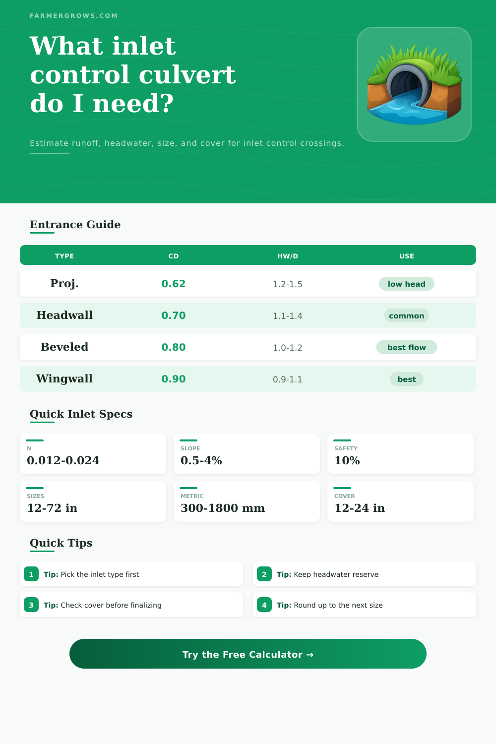
The type of entrance of the culvert will impact the amount of water that can enter the culvert. For instance, if the culvert features a projecting pipe end, some of the debris that enters the culvert may become entrapped between the culvert and the entrance of the culvert. Additionally, only 60 percent of the potential flow of water can enter the culvert through these types of entrances.
Alternatively, if the entrance features beveled inlets and headwalls and wingwalls, the entrance of water into the culvert will be smoothed, reducing the likelihood of entrainment of debris. Additionally, 90 percent of the potential flow of water can enter the culvert through these entrances. Thus, because the beveled inlet is more efficient than the projecting pipe end, more water can enter the culvert.
Another factor that can impact the amount of water that can pass through a culvert is the material of the culvert. The Manning’s n-value of the material can influence the efficiency of the culvert. For instance, if the culvert is constructed of smooth materials like concrete or HDPE, the n-value will be lower (approximately 0.012), indicating that the material of the culvert is smooth and allow the water to glide through the culvert efficient.
In contrast, corrugated metal pipes has a higher n-value (approximately 0.024), indicating that the metal culvert is less smooth and may require a larger diameter pipe for the same amount of flow as a smooth culvert. In addition to considering the factors that impact the efficiency of the culvert, another consideration in the design of the culvert is its capacity in relation to the calculated design flow of the culvert. You must calculate the design flow to ensure that the inlet-limited capacity of the culvert is able to meet the design flow of the culvert.
Additionally, the velocity of the flow must be checked to ensure that the velocity will not result in erosion of the culvert. It is helpful to ensure that the culvert can handle extra flow by providing a margin of at least 15 percent above the calculated design flow. Finally, it is also helpful to incorporate sediment trap in the area upstream of the culvert and use riprap at the outlet of the culvert.
These two features will help to ensure that the culvert does not get clogged with sediment, as well as that the outlet of the culvert does not become turbulent.