Hydraulic Cylinder Angle Calculator
Use pin spacing, stroke, and pressure to check angle, length, and thrust in one pass.
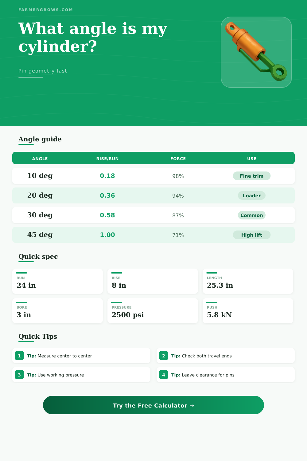
| Angle | Rise/Run | Force kept | Typical use |
|---|---|---|---|
| 10° | 0.18 | 98% | Fine trim |
| 20° | 0.36 | 94% | Loader work |
| 30° | 0.58 | 87% | Common swing |
| 45° | 1.00 | 71% | High lift |
| Machine | Run | Rise | Note |
|---|---|---|---|
| Loader curl | 18-28 in | 4-12 in | Fast bucket |
| Top link | 14-22 in | 2-8 in | Fine trim |
| Dump hoist | 30-44 in | 12-28 in | Steeper lift |
| Thumb | 10-18 in | 4-10 in | Tight swing |
| Bore | Area | 2500 psi | Comment |
|---|---|---|---|
| 2.0 in | 3.14 sq in | 7850 lbf | Compact |
| 2.5 in | 4.91 sq in | 12270 lbf | Medium |
| 3.0 in | 7.07 sq in | 17670 lbf | Common |
| 4.0 in | 12.57 sq in | 31415 lbf | Heavy lift |
| Measure | Imperial | Metric | Note |
|---|---|---|---|
| Length | 1 in | 25.4 mm | Base unit |
| Area | 1 sq in | 645.2 sq mm | Square space |
| Pressure | 1 psi | 0.069 bar | Working load |
| Force | 1 lbf | 4.45 N | Line push |
Pin-to-pin geometry is another critical detail to consider when designing or purchasing a hydraulic cylinder for a machines. If you dont choose the angle of the hydraulic cylinder correctly, the thrust that the cylinder can produce will decrease, or the cylinder will bind within its mount when the machine is under a loads. Because machines do not work in straight lines, the cylinders must be mounted at an angle to provide the proper lift or push for that applications.
The horizontal distance between the pins on a hydraulic cylinder is referred to as the runs. The vertical rise of the cylinder are the height. Using these two measurements, you can calculate the length of the cylinder pin to pin using the Pythagorean theorem.
How to Measure Pin-to-Pin and Set the Angle of a Hydraulic Cylinder
If the pin-to-pin length of the cylinder isnt correctly matched with the machine design, two outcome can occur: the cylinder will not fully retract, or the cylinder will overextend and place excess stress on its mounting structure. A calculator may be used to calculate the pin-to-pin length of the cylinder to avoid any mistake. People often make mistakes when calculating the pin-to-pin length of a cylinder.
A common mistake is measuring from the edges of the mounting ears. By measuring from the edges, you introduce an error of half of the diameter of the pin into you measurements. This introduction of error into your calculations will make your calculations incorrect.
To avoid this error, always measure from the center of the pin to the center of the pin. The angle of the hydraulic cylinder is crucial to the efficiency of that cylinder. The force created by the cylinder acts as a vector, splitting into the horizontal push and the vertical lift of the cylinder.
At 0 degrees, the cylinder will provide 100% of its force in the horizontal direction. At 30 degrees, the horizontal push will be 87% of the force of the cylinder, and 13% will be used to lift the machine. At 45 degrees, the horizontal push will be 71% of the total force created by the hydraulic cylinder.
This indicates that a steep angle is suitable for applications that require lifting, but shallow angles are appropriate for those that require the hydraulic cylinder to push or curl the loads. The force that the cylinder can create is based off the size of the cylinder’s bore and the working pressure of the hydraulic system. The area of the cylinder’s bore is the radius of the bore squared multiplied by pi.
That area multiplied by the working pressure will reveal the raw force that the cylinder can produce while extending. The retraction force is the bore area minus the area of the rod. However, the angle at which the cylinder is mounted will reduce the effective push that the cylinder can make.
That effective push is the extension force of the cylinder times the cosine factor of the angle of the cylinder. Using this information, a cylinder with a 3-inch bore that can produce 2500 psi will have a raw force of 17,000 lbs. However, if you mount that cylinder at 30 degrees, the horizontal push will be 15,000 lbs.
The stroke of the cylinder must be considered when designing a machine. The stroke should be divided by the pin-to-pin length of the cylinder to find the ratio of the cylinder. If that ratio is 50% or under, the hydraulic cylinder will remain in a safe position and will not overtravel.
However, if that ratio is too low, the hydraulic cylinder will lose its travel arc. A common mistake in the selection of a hydraulic cylinder for a machine is producing a stroke that is 20% more long for the machine’s geometry. In such a case, the hydraulic cylinder will extend and retract correctly.
However, when the cylinder is extended, it will slam into the stops set into the machine. This slamming can crack the welds into the machines frame. Additionally, the travel of the cylinder must be considered at both ends of the cylinder.
The cylinder will shorten by 1 to 2 inches when the cylinder is collapsed from rod end to clevis. The number of degrees that the hydraulic cylinder should be mounted at will depend on the function of the machine that uses the cylinder. Snowplows use shallow angle at around 10 degrees to allow for the creation of maximum side force to push through the snow.
Grapples require a steeper angle of around 30 degrees to allow for maximum gripping force to be applied to the load. Log splitters use a nearly horizontal position with an angle of around 4 degrees to allow the machine to exert the full pushing power of the hydraulic cylinder into the log wedge. In these cases, an angle that is too steep for a thumb cylinder will stall the cylinders movement when it attempts to grip the load.
Similarly, the angle will be too shallow for a hoist with a load that require a quick dumping rate. When installing a hydraulic cylinder into a machine, there are a few other considerations that a designer must make. The first of these considerations is clearance.
The stroke of the hydraulic cylinder plus an additional 10% of space must be provided for the hydraulic cylinder. If you dont allow the hydraulic cylinder to expand to reach that additional length, the frames of the machine will be scarred. Additionally, pins will require grease zerks and bushings to provide lubrication for the pin.
Due to the angle at which the cylinder is mounted, the plain bore of the pin can wear quickly. The working pressure that the hydraulic system uses must also be considered. Pressure spikes that occur in a hydraulic system can destroy the seal that are inside the cylinder.
Therefore, 20% must be derated from the working pressure to allow for the safety of the hydraulic system. Finally, the angle input for the hydraulic cylinder must be checked to ensure the error is minimal. If the error in angle measurement for the hydraulic cylinder is under 2 degrees, the hydraulic cylinder is correctly mounted to the machine.
However, if the angle error is over 5 degrees, the hydraulic cylinder must be remounted to the machine.