Foul Drainage Falls Calculator
Estimate foul drain fall, gradient, downstream invert, hydraulic capacity, self-cleansing velocity, fixture load, and access spacing for farm buildings, yards, extensions, and private drains.
Use this as a design check before setting out trenches. It follows common UK foul drainage practice and references Part H style minimum gradients, but final layouts should be confirmed against site levels, local approval, soil conditions, and the receiving sewer or treatment plant.
Drainage Fall Results
The hydraulic card uses Manning flow at 0.75 proportional depth, which is the same depth basis used for common foul drain capacity charts.
| Peak flow condition | Pipe size | Minimum gradient | Fall per metre | Maximum capacity | Use note |
|---|---|---|---|---|---|
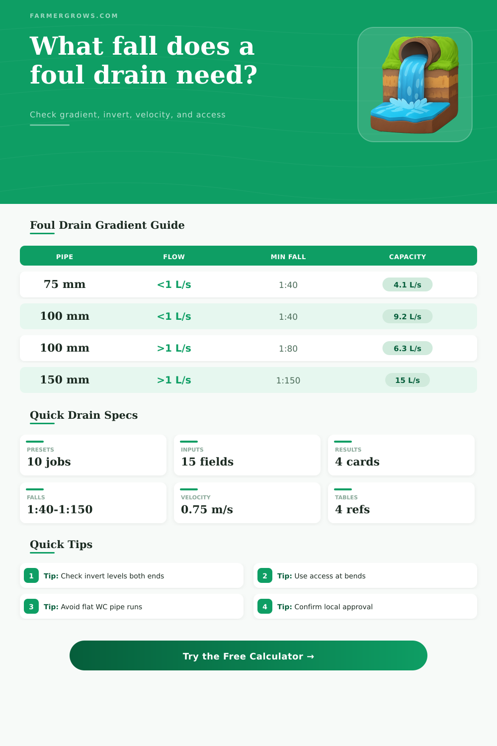
| Less than 1 L/s | 75 mm | 1:40 | 25.0 mm/m | 4.1 L/s | Foul drain with no WC discharge unless separately justified |
| Less than 1 L/s | 100 mm | 1:40 | 25.0 mm/m | 9.2 L/s | Short domestic or small building foul drain |
| More than 1 L/s | 75 mm | 1:80 | 12.5 mm/m | 2.8 L/s | Small foul drain without large solids load |
| More than 1 L/s | 100 mm | 1:80 | 12.5 mm/m | 6.3 L/s | Part H note: minimum of one WC |
| More than 1 L/s | 150 mm | 1:150 | 6.7 mm/m | 15.0 L/s | Part H note: minimum of five WCs |
| Run length | Fall at 1:40 | Fall at 1:60 | Fall at 1:80 | Fall at 1:100 | Fall at 1:150 |
|---|---|---|---|---|---|
| 5 m | 125 mm | 83 mm | 63 mm | 50 mm | 33 mm |
| 10 m | 250 mm | 167 mm | 125 mm | 100 mm | 67 mm |
| 15 m | 375 mm | 250 mm | 188 mm | 150 mm | 100 mm |
| 20 m | 500 mm | 333 mm | 250 mm | 200 mm | 133 mm |
| 30 m | 750 mm | 500 mm | 375 mm | 300 mm | 200 mm |
| 50 m | 1250 mm | 833 mm | 625 mm | 500 mm | 333 mm |
| Fixture or building group | Design flow | Calculator input | Trap or pipe context | Practical note |
|---|---|---|---|---|
| 1 dwelling group | 2.5 L/s | Dwelling equivalent | WC, bath, basin, sink, washer | Used by Part H for typical domestic grouping |
| 5 dwelling groups | 3.5 L/s | Dwelling equivalent | Small shared private drain | Flow rises slowly because simultaneous use is limited |
| 10 dwelling groups | 4.1 L/s | Dwelling equivalent | Larger shared drain | Check sewer ownership and adoption rules early |
| Spray tap basin | 0.06 L/s each | Extra basins | 32 mm or 40 mm branch | Small continuous allowance for grouped basins |
| Washing machine | 0.70 L/s each | Extra washers | 40 mm trap common | Use as extra load beyond any dwelling group |
| Dishwashing machine | 0.25 L/s each | Extra dishwashers | 40 mm trap common | Useful for farm shop, kitchen, or tea room checks |
| Urinal position | 0.15 L/s each | Urinal positions | 50 mm or 65 mm branch | Part H appendix value per person position |
| Access situation | Small fitting | Large fitting | Junction | Inspection chamber | Manhole |
|---|---|---|---|---|---|
| Start of external drain | 12 m | 12 m | Use at junction | 22 m | 45 m |
| From rodding eye | 22 m | 22 m | 22 m | 45 m | 45 m |
| From small access fitting | Not used | 12 m | 22 m | 22 m | 22 m |
| From large access fitting | Not used | 22 m | 45 m | 45 m | 45 m |
| From shallow inspection chamber | 22 m | 45 m | 22 m | 45 m | 45 m |
| From deep chamber or manhole | Not used | Not used | Not used | 45 m | 90 m |
| Check item | Formula or rule | Good result | Watch if |
|---|---|---|---|
| Gradient | 1:N = run / fall | Meets or exceeds Part H minimum | N is larger than the recommended minimum route |
| Total fall | Run length / N | Outlet invert is still above receiving invert clearance | Fall consumes too much cover at the downstream end |
| Pipe velocity | Manning velocity at 0.75 depth | At or above 0.75 m/s for foul self-cleansing | Flat pipe, rough material, or oversized pipe lowers velocity |
| Capacity margin | Design flow / calculated capacity | Below 80% for routine design allowance | More than 100% means the pipe is overloaded |
| Access spacing | Run length / spacing limit | Access at head, bends, junctions, changes, and long runs | Any run cannot be cleared by normal rodding |
Invert levels: Set out from the receiving chamber or treatment plant as well as from the building. A beautiful gradient is useless if the outlet invert arrives too low or with poor cover.
Access points: Put chambers or rodding access at the head of the run, bends, junctions, pipe-size changes, and gradient changes. Long straight farmyard runs still need clearable spacing.
Achieving the correct fall for a foul drain is a task in which make a small error can lead to an expensive problem in the future. If the foul drain dont have enough fall, the solids will settle within the foul drain and create a blockage. If the foul drain has too much fall, then the cover will likely fall off the foul drain, leading to damage from the ground traffic or frost.
It is important to determine the fall that a foul drain of a specific length can carry, as the fall must meet the requirements created by the volume of the expected flows within the foul drain. One of the main factor to consider is the size of the pipe and the load that it will carry. For instance, a 100 mm pipe that drains the waste from a single house will require a more different fall than a 100 mm pipe that drains a farm building that contain a variety of appliances.
How to Find the Right Fall for a Foul Drain
The amount of water that will pass through the pipe will impact the required fall for that specific pipe. If the flow of water are to be low, the engineer will have to make the fall of the foul drain steeper to allow the solids to move through the pipe. In contrast, high volume of water will allow for a lower gradient within the foul drain.
A calculator allow for the engineer to enter the size of the foul drain, the length of the foul drain, and the number of appliance into the system to determine the fall that will achieve the desired flow. Another of the factors to consider is the ground. The calculations may indicate the fall that the foul drain should have, but the trench may cross a slope, hit rock, or cross a service road.
In these situations, the engineer will have to decide if the engineer should adjust the foul drain route. A calculator will give the target fall and the target outlet invert, but the engineer will have to make a decision regarding adjustments to the route of the foul drain. Additionally, the cover of the foul drain should be considered.
If the calculations indicate that the foul drain will barely have enough depth to incorporate the required cover for the foul drain, that is a warning signal for the engineer to inspect the area for any possible protection for the foul drain. Access to the foul drain should also be considered. The location of the foul drain may be visually appealing to the sewer or sanitary engineer, but it may not provide enough access for any maintenance activities.
The foul drain may include long straight runs between the building it services. Long straight runs of a foul drain can make it difficult to remove any possible solid that may have become impacted within the foul drain. The tool allow for an engineer to enter the spacing between the buildings to determine the number of foul drain access point that will be required along the route.
This number the sewer engineer can then use when placing inspection chambers or rodding eyes along the route of the foul drain. The type of material that the sewer engineer should consider to construct the foul drain is another factor. The flow that move through a smooth plastic foul drain will experience less friction than a foul drain constructed of clay or concrete.
Thus, the velocity of the flow will be higher in the plastic foul drain. The difference between the two materials is unlikely to impact the foul drain design process, but it is important to consider the effect of the material on the flow within that foul drain. A calculator tool for foul drain allows the engineer to switch between the different roughness value for the different foul drain materials to see the effect that they could have on the foul drain.
There are a variety of small trade-off that will have to be made in the foul drain design process because there is no perfect answer for foul drain design. The engineer will have to consider the flow in the foul drain, the gradient of the foul drain, the cover over the foul drain, the access to the foul drain, the future maintenance of the foul drain, and a variety of other factor. By using the foul drain calculator, the engineer can determine the various gradients and flows that is possible within the foul drain.
By running these calculations early in the foul drain design process, the engineer can determine which combinations will require compromises to the specifications of the foul drain. Once the foul drain is dug into the ground, it will be difficult and costly to make changes to the fall of the foul drain. Thus, the calculations at the beginning of the foul drain design process are a worthwhile activity.