Air Hose Pressure Drop Calculator
Estimate compressed-air PSI loss through hose length, inside diameter, fittings, temperature, material, and compressor duty before the tool starts starving for pressure.
This calculator uses a Darcy-Weisbach style compressed-air approximation: SCFM is converted to actual line flow, hose friction is estimated from material roughness, and fittings are added as equivalent hose length plus small connector losses.
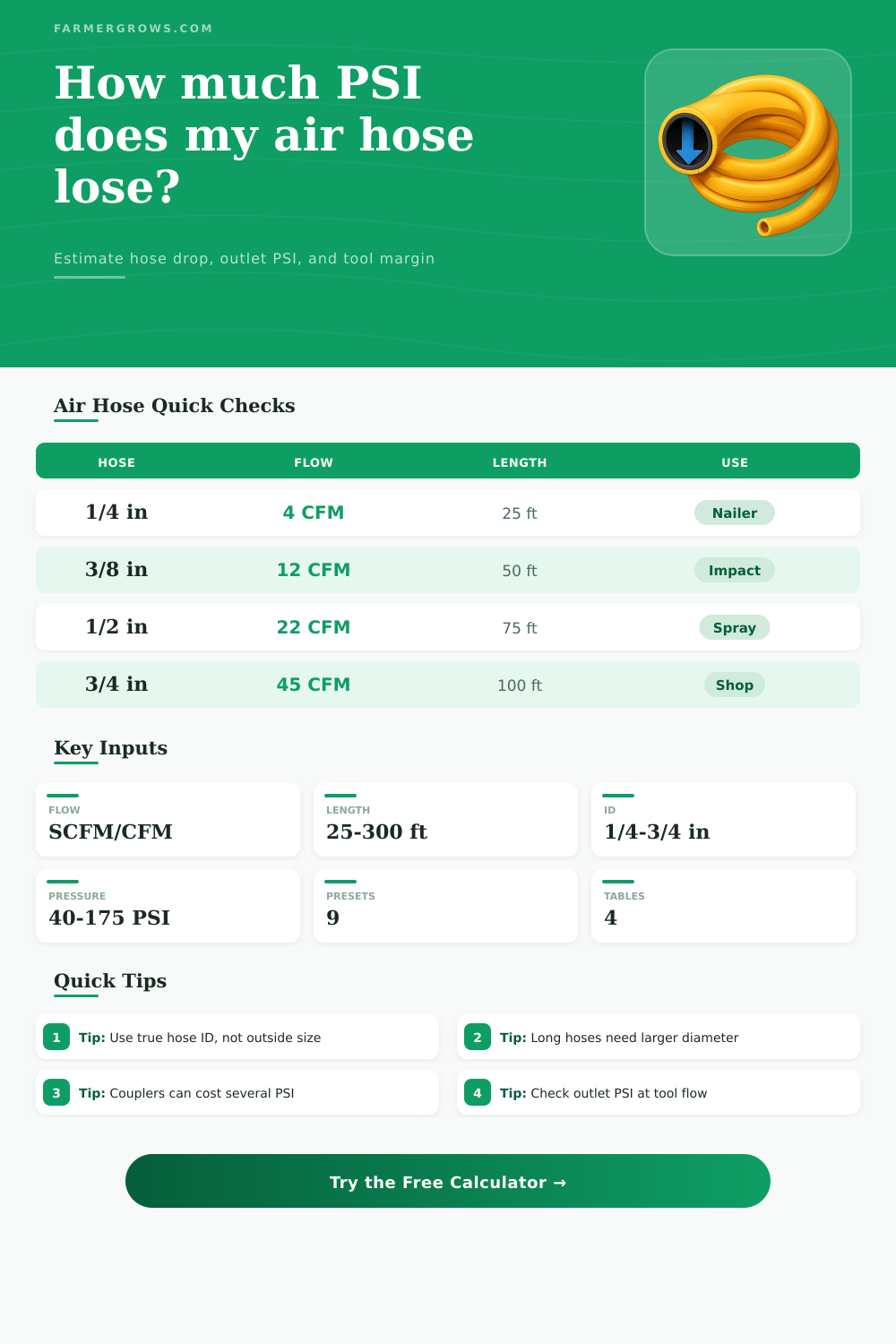
Short bursts tolerate small hose, but long 1/4 in runs can still slow recovery at low tank pressure.
A 3/8 in hose is the practical minimum when the tool needs fast hits and 90 PSI at the handle.
Spray patterns show pressure sag quickly, so larger ID and fewer couplers help keep steady atomization.
High continuous demand usually needs 1/2 in or 3/4 in hose and a compressor with high duty capacity.
Pressure Drop Results
Your hose estimate will appear here.
| Hose ID | Best flow range | Typical length | Pressure-drop warning sign |
|---|---|---|---|
| 1/4 in | 2-5 SCFM | 25-50 ft | Good for nailers; restrictive for impacts and grinders. |
| 5/16 in | 4-8 SCFM | 25-75 ft | Useful compromise when weight matters more than peak flow. |
| 3/8 in | 8-15 SCFM | 50-100 ft | Common shop size for impacts, inflators, and medium tools. |
| 1/2 in | 15-30 SCFM | 50-150 ft | Better for paint, grinding, and longer farm or shop runs. |
| 3/4 in | 30+ SCFM | 100-300 ft | Use for high-demand manifolds, blasting, and trunk lines. |
| Tool | Typical SCFM | Tool PSI target | Hose note |
|---|---|---|---|
| Brad or finish nailer | 2-4 | 70-100 PSI | Short 1/4 in hose is usually acceptable. |
| Framing or roofing nailer pair | 5-9 | 90-120 PSI | Use 3/8 in when two users share one line. |
| 1/2 in impact wrench | 8-12 | 90 PSI | 3/8 in minimum; 1/2 in helps with long runs. |
| Die grinder | 10-16 | 90 PSI | Continuous use punishes small hose quickly. |
| HVLP spray gun | 12-18 | 25-45 PSI at gun | Keep fittings clean and verify pressure while flowing. |
| Blast cabinet | 20-45 | 80-100 PSI | Large hose and high continuous compressor output matter. |
| Fitting type | Equivalent hose length | Added minor loss | Practical note |
|---|---|---|---|
| Quick coupler pair | 6 ft each | 0.8 PSI each | Small automotive plugs can be the hidden bottleneck. |
| Elbow, tee, or swivel | 3 ft each | 0.25 PSI each | Useful allowance for bends near reels and manifolds. |
| Inline regulator or filter | 10 ft each | 1.5 PSI each | Measure at flowing air because static gauges hide drop. |
| Hose reel path | 15-30 ft | Varies | Undersized reel cores can act smaller than the hose ID. |
| Material | Friction factor used | Best use | Pressure-drop behavior |
|---|---|---|---|
| Rubber | 0.026 | General shop and farm use | Durable, flexible, slightly higher friction when aged. |
| Hybrid polymer | 0.023 | All-weather utility hose | Good balance of flexibility and smooth bore. |
| Polyurethane | 0.022 | Lightweight trim work | Smooth, light, but often small ID for high flow. |
| PVC | 0.025 | Budget shop hose | Can stiffen in cold air and kink into extra restriction. |
| Nylon tubing | 0.020 | Fixed lines and controls | Smooth bore, but fittings and ID still control losses. |
Check tool pressure while air is flowing. Static gauges can look fine even when a coupler or reel drops several PSI under load.
If outlet pressure is close to the tool minimum, step up one hose ID before raising regulator pressure.
When a compressor is place in one location in a shop and a tool is placed in an another location, the air pressure that reaches that tool may be lower than the air pressure that was set on the regulator of the compressor. As the air travel from the compressor to the tool, it can lose some of its energy due to friction within the air hose. Any couplers, elbows, or changes to the diameters of the air hose will also contribute to the loss of air pressure.
The longer the air hose or the smaller the diameter of that hose, the more air the air will lose as it travel from the compressor to the tool. Tools that require 90 or 100 PSI will not be able to perform as well as tools that require lower air pressure levels due to these losses of air pressure. Tools that are continuous used will exhibit the effects of air pressure loss.
Why Air Pressure Drops in Hoses and How to Fix It
Tools like die grinders will slow down if the air pressure drop 10 PSI from the requirements of the tool manufacturer. Spray gun will also be affected by the loss of air pressure. Nail guns will not exhibit the effects of air pressure loss right away as they fire in bursts.
However, as the air pressure from the compressor must recover the lost pressure to the tool, the compressor will run longer and will run hotter than if it were using an appropriately size air hose. There are various inputs that will impact the losses of air pressure within the air hose. The flow demand of the tool will impact air pressure loss.
For example, framing nailers may require 4 or 5 SCFM while a blast cabinet may require 25 SCFM. The diameter of the inside of the air hose will impact the air losses due to friction. A 1/4 inch air hose may be sufficient for the air requirements of a tool that have low air demands.
However, 1/4 inch air hose may not be able to supply enough air to a tool that requires high air flow rate if the length of the hose is 50 feet. The length of the air hose and the temperature of the air within the hose will also have an impact on air pressure loss due to friction. Additionally, the inlet air pressure will also impact the air pressure losses within the air hose.
Air hose fittings will also cause losses of air pressure. These fitting are often underestimated in their impact on air pressure. Each quick coupler will lose some air pressure.
Two quick couplers can cause more loss in air pressure than a long air hose. Elbows and inline regulators can also cause losses of air pressure within the air hose. A calculator is available that will help determine the equivalent length of air hose caused by each fitting.
The air compressor’s capacity and the air compressor’s duty cycle will impact the air supply to the tool. The air compressor will need to be able to supply the air that the tool consume. For instance, if the air compressor can deliver 15 SCFM but has a 70% duty cycle, it will only be able to deliver 10.5 SCFM of continuous air.
If the air requirements of the tool and air hose exceed the air that the compressor can deliver, the air tank’s pressure will drop over time. A calculation will reveal whether or not the air compressor is sized for the actual load of the tool or only sized for the nameplate number of the tool. The material of the air hose will create friction within the air hose.
Rubber shop air hose will have more friction within the hose than air hoses made of a hybrid polymer or polyurethane. The difference in air pressure loss between these two type of air hose is small if the air hose is short in length. However, the difference becomes more measurable over longer distance of air hose.
Additionally, the temperature of the air within the air hose will also impact the friction within the hose. Hotter air will have less friction within the air hose than colder air. However, cold air may cause the air hose to become stiffer which could lead to kinks in the hose which will restrict the movement of air through the hose.
The two main outputs of air pressure loss in an air hose are the total pressure drop within the hose and the estimated outlet pressure at the tool. The total pressure drop is an important measurement of the losses of air pressure. However, the estimated outlet pressure at the tool is the more important of the two figure.
If the estimated outlet pressure is above the minimum requirement for the tool, the air pressure is within a range that will allow for changes in air temperature or additional couplers. If the estimated outlet pressure is within or below the minimum requirement for the tool, it indicates that the system is in a marginal state. Any additional restriction on the air hose will reduce the performance of the tool.
High velocities of air near the wall of the air hose can cause turbulence in the air movement which waste energy and creates noise within the air hose. In most shops, the air hose will not be run in a single line from the air compressor to the tool. Instead, air hoses will have reels, manifolds, and quick changes in the air hose.
Each of these addition will increase the length of the air hose and the number of air hose fittings. Each time a shop purchase an air tool with quick couplers, that quick coupler will add length to the air hose that must be considered in the calculation of the total pressure drop of that air hose. One mistake that shops often make is to increase the regulator pressure on the air compressor to compensate for the losses of air pressure within the air hose.
However, increasing the air pressure at the regulator will only work until the air compressor reaches its limit. Beyond that limit, the air tank will not be able to maintain the high air pressure. Instead of increasing the supply air pressure, restricting the system will help the tool to maintain adequate air pressure at the tool.
Using a larger air hose or reducing the number of air hose fittings will fix the air pressure loss problem. Additionally, reducing the average air pressure will also reduce the wear of the air compressor and the amount of energy that it will use. Another mistake that some shops make is to treat the drop in air pressure as a fixed aspect of the air hose.
However, the air pressure drop will change with changes in air flow rate, inlet air pressure, and air temperature within the air hose. For example, air pressure drop may change if the same air hose is used on a hot day as compared to a cold day. Using an air pressure loss calculator will reveal the impact of these different variable.
Knowing the impact of these variables will allow the shop to make changes to the system that will lead to improvements in the air system. The goal is to lose some air pressure within the air hose, but not too much. The goal is to ensure that the tool remain within its working range and that the air compressor remains within its air compressor duty cycle.
If the air tool and air compressor are maintained within their specified ranges, the air system will function efficiently.