Submersible Pump Stage Calculator
Estimate total dynamic head, required pump stages, water horsepower, brake horsepower, and motor loading for well pumps, irrigation sets, stock-water systems, and farm transfer lines.
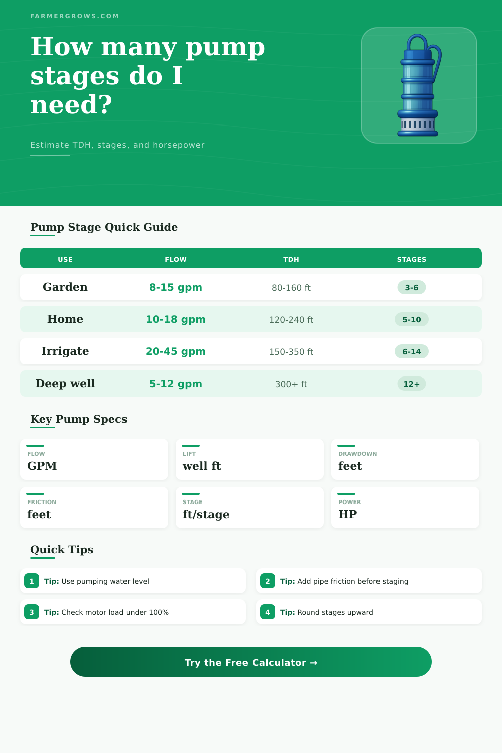
Enter the head components in feet. This calculator treats well depth as the vertical lift to the pumping water level, then adds drawdown, target delivery head, pipe friction, and a safety margin before rounding the number of stages upward.
Submersible Pump Stage Results
Enter flow, head, stage, and motor values to estimate stage count and horsepower.
| Pump style | Common flow range | Typical head per stage | Best use |
|---|---|---|---|
| 4 inch residential | 5–18 GPM | 18–35 ft/stage | Homes, gardens, and small stock tanks. |
| 4 inch high head | 3–12 GPM | 30–55 ft/stage | Deep wells with lower flow needs. |
| 6 inch farm well | 20–75 GPM | 15–40 ft/stage | Irrigation headers and larger trough systems. |
| Turbine bowl stack | 50+ GPM | 20–60 ft/stage | High-flow farm supply and transfer wells. |
| Component | How to enter it | Typical range | Stage impact |
|---|---|---|---|
| Well lift | Depth to pumping water level or conservative vertical lift. | 40–400 ft | Usually the largest part of TDH. |
| Drawdown | Extra drop during pumping at design GPM. | 5–80 ft | Raises stage count when the well pulls down. |
| Target head | Pressure need, tank height, field elevation, or emitter pressure. | 30–160 ft | Adds directly to TDH before safety margin. |
| Friction loss | Pipe, fittings, valves, filter loss, and manifold restriction. | 5–90 ft | Often underestimated on long farm runs. |
| Calculated brake HP | Next common motor | Motor loading target | Check before choosing |
|---|---|---|---|
| 0.4–0.7 HP | 0.75 HP | 55–90% | Confirm minimum cooling flow past the motor. |
| 0.8–1.1 HP | 1.5 HP | 55–85% | Confirm voltage drop and starting current. |
| 1.2–2.0 HP | 2 or 3 HP | 60–90% | Check wire size, control box, and overload range. |
| 2.1–5.0 HP | 3 to 7.5 HP | 60–90% | Use the pump curve and motor service factor. |
| Scenario | Flow target | Common TDH band | Stage planning note |
|---|---|---|---|
| Garden and hose bib supply | 8–15 GPM | 80–180 ft | Pressure head can exceed the well lift. |
| Livestock trough refill | 6–20 GPM | 100–260 ft | Storage tank height and long pipe runs matter. |
| Drip irrigation header | 15–35 GPM | 130–300 ft | Filters and pressure regulators add head loss. |
| Orchard or field block | 25–60 GPM | 180–380 ft | Higher GPM can lower head per stage on the curve. |
Curve tip: Head per stage changes with flow. Use the value at your design GPM from the pump curve instead of a catalog maximum.
Well tip: Use pumping water level after drawdown when available. Static water level alone can undersize the stage stack and overload the motor.
A well pump may lose pressure during the season, and you may have to determine the correct number of stage for the well pump. The number of stages for the well pump is the number of impeller located within the stainless steel housing of the pump. The correct number of stages is not easily determined, though, because four separate parts comprised the total dynamic head for the well that can change from well to well.
The first part of the total dynamic head is the lift, which is the distance from the water level in the well to the point of discharge. This lift increases if the water level within the well drop. The static depth of the well may not accurately reflect this lift measurement.
How to Find the Right Number of Stages for a Well Pump
The second part of the total dynamic head is the surface pressure, which is the pressure required at the surface of the well at points like a pressure tank, irrigation manifold, or storage tank. The third part of the total dynamic head is the friction loss in the system, which result from the resistance of the water within the pipes, check valves, and filters in the water system. The last part of the total dynamic head is the pressure that is required at the discharge point of the well.
By calculating each of these four parts of the total dynamic head, you can divide the result by the head that each stage of the pump can deliver at a given flow rate. A pump curve demonstrate the flow rates of a well pump. Pump curves indicate that the head that each stage of the pump delivers decreases as the flow rate of the pump increase.
A flow rate increase with a larger impeller diameter will require more stages for the pump. Using a stage with a high head will result in high pressure at the tap for a low flow rate of the well. This calculator will assist in determining the correct number of stages for the well pump by comparing the brake horsepower of the pump to the horsepower of the motor that is install in the pump.
By comparing these two value, it is possible to determine if the calculated number of stages will overload the motor windings of the motor or if the motor will remain within it’s service factor. A farmer may have to use the well for both the house and the irrigation system. The friction loss for the water used for the house will be relatively low; however, the friction loss will be higher for the irrigation system.
By using the calculator, it is possible to determine if the current well pump will be able to handle both the house and the irrigation system or if a second pump will be require. Efficiency in a well pump is not a fixed number. Efficiency is a specific point on the pump curve.
If the well pump have a low efficiency, it will have to work harder to deliver the same volume of water as a more efficient pump. For instance, if the well pump has an efficiency of 45 percent instead of 65 percent, the motor will have to deliver more brake horsepower to the pump. The higher the brake horsepower that the motor has to deliver, the hotter the motor will become.
Excessive heat of the motor housing is problematic if there isnt enough water cooling the motor housing. This calculator will ask for the efficiency of the pump and use that number to calculate the motor load. Wells change over time.
As wells age and as water from the well becomes mineral scaled, the diameter of the drop pipe can decrease. Additionally, the friction loss within the system may increase due to the mineral scale in the system. The friction loss in the system may also increase due to the age of the check valve.
These change may occur gradually such that the well pump may continue to run even if the total dynamic head increases. A safety margin may be included to calculate the number of stages in the pump, but it is not a replacement for testing the flow and the pressure of the well. The size of the motor that is used for the well pump should be the smallest that the motor can be while maintaining a motor load under 100 percent of the motors specifications.
A 15 percent reserve is typically included in the calculation of the load on the motor because motor manufacturers recommend a 15 percent reserve. The motor may lose its ability to cool the motor housing on a hot day if the level of water in the well drop. The water that cools the motor creates a flow of water past the motor housing.
If the level of the water in the well drop, there will be less flow of water past the motor housing that cools the motor. To avoid having to schedule service calls on the pump for the house or the irrigation system, it may be better to choose a slightly larger motor for the pump. The reference tables that are provided with the calculator list the head in feet per stage that a well pump can deliver within certain diameter sizes of impeller and flow rates.
These values are not rule. However, they provide a sense of whether or not the calculated number of stages for the well pump is realistic. For instance, a 4-inch well pump that is used in residential properties rarely will deliver more than 35 feet of head per stage at a flow rate of 12 gallons per minute.
If the pump curve for the well indicates that the pump can deliver 22 feet of head per stage but the calculation of the total dynamic head indicates that 18 stage are required for the pump to deliver the necessary flow rate, the total dynamic head calculation may have underestimated the friction losses that will be experienced by the system or the wrong pump size may have been chose. The number of stages in the well pump is a compromise between the power of the motor and the physical characteristic of the well. The calculator turns four values and one value from the pump curve into a single number that represents the number of stages of the well pump.
The number of stages determine other choices in installing and operating the pump.