Exhaust Fan Duct Size Calculator
Size round or rectangular exhaust ducting from fan CFM, target duct velocity, equivalent length, elbows, static pressure, and a noise limit for grow rooms, greenhouses, barns, and drying spaces.
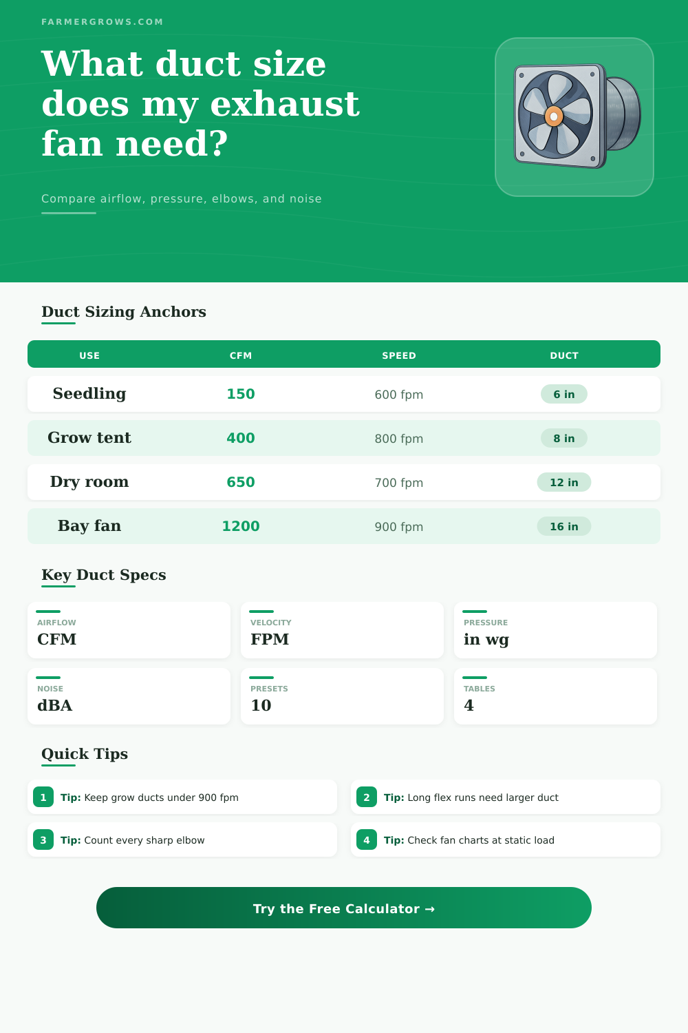
Use the presets to start with a real farm or grow-space exhaust profile, then tune the duct shape, size, run length, fittings, and fan-side static pressure.
Duct sizing result
Enter the fan airflow and installed duct details to estimate area, velocity, static pressure, and noise fit.
Calculate to compare velocity and pressure.
Calculate to compare velocity and pressure.
Calculate to compare velocity and pressure.
Calculate to compare velocity and pressure.
| Application | Quiet Range | Balanced Range | Watch Point |
|---|---|---|---|
| Seedling tent or propagation shelf | 400 to 650 FPM | 650 to 800 FPM | Keep duct and fan hum low near plants. |
| Grow tent or filtered exhaust | 550 to 800 FPM | 800 to 1000 FPM | Carbon filters often set the fan curve limit. |
| Greenhouse or barn wall exhaust | 700 to 1000 FPM | 1000 to 1300 FPM | Use larger duct when people work nearby. |
| Short utility exhaust duct | 900 to 1200 FPM | 1200 to 1600 FPM | High speed can whistle at louvers and bends. |
| Duct Type | Loss Factor | Noise Bias | Best Use |
|---|---|---|---|
| Smooth galvanized metal | 1.00x | Base | Long permanent greenhouse and barn exhaust runs. |
| Lined metal duct | 1.08x | Lower | Quiet crop rooms where insulation is useful. |
| Short stretched flex | 1.28x | Medium | Short fan connections with gentle bends. |
| Long or sagging flex | 1.65x | Higher | Avoid for high CFM unless upsized generously. |
| Elbow Style | Typical Add | Noise Effect | Use In Calculator |
|---|---|---|---|
| Smooth radius elbow | 6 to 10 ft | Low | Use 8 ft when bends are gradual. |
| Standard adjustable elbow | 10 to 15 ft | Medium | Use 12 ft for common metal elbows. |
| Tight stamped elbow | 18 to 25 ft | High | Use 20 ft for compact turns. |
| Flex duct bend | 15 to 30 ft | High | Use more when the bend is kinked or sagging. |
| Component | Typical Static | When It Rises | Sizing Note |
|---|---|---|---|
| Clean louver or shutter | 0.03 to 0.08 in wg | Small opening or insect screen | Add before checking fan chart airflow. |
| Carbon or dust filter | 0.10 to 0.35 in wg | Dense media or loaded filter | Often the largest grow-room restriction. |
| Backdraft damper | 0.03 to 0.12 in wg | Light fan pressure or sticky blades | Verify it opens at low speed. |
| Long duct run | Varies by size | High velocity or rough flex | Upsize duct to reduce friction loss. |
Tip: Size the duct from the delivered CFM, then confirm the fan still delivers that CFM at the total static pressure shown on its fan curve.
Tip: If the noise card fails, try a larger duct before lowering airflow; velocity and tight elbows usually create the sharpest duct noise.
Exhaust fans will moves air through a system, but the air will experience resistance as it has to move through the ducts of the exhaust fan systems. When the air moves through a duct, it experiences friction against the duct walls, and the air has to move around the bend in the duct. Therefore, the size of the duct that are chosen for an exhaust fan will determine whether the fan system is quiet and efficient or loud and inefficiently.
If the duct that is used with an exhaust fan is the incorrect size, the exhaust fan may whine, the motor may overheat, or the exhaust fan may fail to effectively clear the area that is to be exhausted. One of the first numbers that you must provide to the exhaust fan duct calculator is the rated airflow of the exhaust fan. The fan manufacturer provides the rated airflow, and is listed in units of cubic feet per minute (CFM).
How to Size Exhaust Fan Ducts
The rated airflow indicates the amount of air that the fan can move through the duct system when tested under ideal conditions. The rated airflow is not the same than the actual airflow that the exhaust fan will deliver. For instance, an exhaust fan that is rated at 650 CFM may only be able to move 420 CFM when the duct system is too small for the fan.
In this case, the rated airflow is an input for the calculator, but so is a target air velocity for the system. Air velocity is the speed of the air that is moving through the exhaust fan system, and it is measured in feet per minute. Higher air velocity mean that the exhaust fan system will be quieter, but it will also create more friction within the duct system.
Lower air velocity creates less friction for the exhaust fan system, but requires a larger duct system to allow the exhaust air to move through the system at that lower velocity. Air velocities between 650 and 900 feet per minute are typically recommended for most utility spaces. However, the higher the velocity that is targeted for the exhaust fan system, the less noise that the system will create, but the more noise that the fan motor may make.
Beyond target air velocity, the calculator considers two additional factor: the length of the duct and the number of fittings along the duct. The number of elbows and turns along the duct increase the resistance to the airflow, so each of these elements is converted into equivalent lengths of the duct in the calculation. The total length of the exhaust fan system will factor into the calculation of the friction loss within the duct system.
Friction within duct systems is expressed in inches of water gauge per 100 feet of duct. Friction increases with increased air velocity, as well as with the roughness of the inner walls of the duct. Each type of duct has a different friction rate.
For example, smooth galvanized metal ducts have different friction rates than lined metal ducts, short flex ducts, long sagging flex ducts, and PVC (polyvinyl chloride) ducts. For example, a flex duct that sags between the supports will create more friction within the duct system than if the same diameter duct was rigid. After calculating the friction rate within the duct system, the calculator calculates the total static pressure of the system.
The total static pressure can be determined by the total static pressure curve of the exhaust fan. Another factor in the calculator is noise levels. Noise levels are an indicator of how well the exhaust fan system is functioning, and is often one of the first factors that individuals who are exposed to the system note.
The calculator estimates the noise of the system, and that estimate is based upon the airflow, the velocity of the air, the number of elbows in the system, and the type of the surface of the duct. If the estimated noise of the system is above the noise level that is targeted, then adjustments to the system will be required. One of the adjustments that can be made is to increase the size of the duct by one size.
Increasing the size of the duct is one of the most common adjustments that will be made to an exhaust fan system, as it is an inexpensive adjustment to the system. Another option for the exhaust fan system is to use a rectangular duct system. Many exhaust fan systems have rectangular openings in the structure in which they are to be installed.
For these applications, the duct calculator can accept the width and height of the rectangular duct system. Based off the width and height, the calculator will calculate the actual velocity of air within the system, as well as calculate an equivalent round duct system that will allow for the same air friction within the rectangular duct system. This equivalent round diameter is calculated so that the formula for friction loss within the system is the same regardless of the shape of the duct.
Rectangular duct systems are often used when the head room within the structure is limited, or the structure within which the duct is to be installed has limited space between the joists in which the exhaust fan is to be installed. Another consideration of exhaust fan systems is the resistance created by other components of the system. For instance, many exhaust systems contain a carbon filter as a means of capturing particles in the air.
The static air pressure created by these filters increases as the filter becomes loaded with particles. Other components of the system that create static air pressure are screens placed on the intake shutters to prevent pests from entering the system. Another component of the system that can create increased static air pressure is a backdraft damper that sticks in its opening.
To account for these different variables, the calculator permits the user to separate the static air pressure that is created by the fan and the duct system from the static air pressure that is created by the friction loss within the duct system. For instance, if the carbon filter becomes dirty, or if the louvers on the intake shutters become dirty, the static air pressure that is created by these dirty components will increase. Therefore, the static air pressure of the fan or the filter can be increased in the calculator to account for this additional static air pressure.
Because the duct system can be complex to size correctly, several mistakes are made in the setup of these exhaust fan systems. For instance, one of the most common mistakes is to purchase the exhaust fan first, and then to discover that the exhaust fan must be connected to a long exhaust flex duct system with numerous tight turns. In this case, the exhaust fan will be working, but the air that it will move will be much less than that which is rated for the fan.
Another mistake is to believe that as long as the size of the exhaust fan’s outlet opening is the same size as the exhaust duct, the fan will perform as desired. For example, the size of the exhaust fan’s collar may be 10 inches in diameter, but the exhaust duct may also be 10 inches in diameter. This may seem like an appropriate solution, but it is not one that will ensure the proper functioning of the exhaust fan.
The purpose of the duct calculator is to ensure that the fan will move enough air, the noise levels will be within acceptable limits, and that the static air pressure will not work against the fan motor. If these three factors are ensured, then the exhaust fan system will function in the desired manner. Thus, the calculator has removed the difficulty of performing the calculations by hand, allowing the focus of the designer of the exhaust fan system to shift to the physical elements of the exhaust system.