Wind Turbine Swept Area Calculator
Estimate rotor swept area, hub-adjusted area, array area, available wind power, and Cp-adjusted turbine output for horizontal-axis and vertical-axis wind turbines.
Choose a starting point, then tune the dimensions, wind speed, air density, power coefficient, and turbine count for your site.
Swept Area and Wind Power Results
The calculator reports gross rotor area, hub-adjusted net area, available wind power, Cp-adjusted rotor power, and array totals.
| Calculation | Formula | Inputs used | Planning note |
|---|---|---|---|
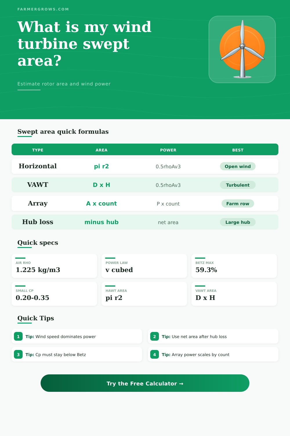
| Horizontal-axis gross area | A = pi x r² | Rotor radius or diameter / 2 | Use the full blade-tip circle before hub deduction |
| Horizontal-axis net area | A = pi x (r² - hub r²) | Rotor radius and hub radius | Useful when hub is large compared with rotor diameter |
| Vertical-axis area | A = diameter x height | Rotor diameter and rotor height | Projected rectangular swept area |
| Array swept area | A total = A x count | Net area and turbine count | Does not replace spacing or wake-loss studies |
| Blade length check | Blade = radius - hub radius | Rotor radius and hub diameter | Helps catch inconsistent rotor dimensions |
| Step | Formula | Units | What it means |
|---|---|---|---|
| Wind power through rotor | P = 0.5 x rho x A x v³ | watts | Total kinetic power in the air stream |
| Rotor mechanical output | P rotor = P x Cp | watts | Power captured by the rotor before electrical losses |
| Usable adjusted output | P usable = P rotor x factor | watts | Optional wiring, inverter, downtime, or availability derate |
| Power density | P / A = 0.5 x rho x v³ | W/m² | Available wind power per square meter of rotor area |
| Betz limit | Cp max = 0.593 | ratio | No rotor can capture all kinetic wind power |
| Reference item | Typical value | Use in calculator | Planning note |
|---|---|---|---|
| Standard air density | 1.225 kg/m³ | Default density | Sea level near 15°C |
| Cool dense air | 1.25 to 1.30 kg/m³ | Higher density input | Can raise power estimate for cold sites |
| Warm or high-elevation air | 1.00 to 1.15 kg/m³ | Lower density input | Reduces available wind power |
| Small horizontal turbine Cp | 0.25 to 0.40 | Cp input | Depends on blade design and generator loading |
| Vertical-axis turbine Cp | 0.15 to 0.35 | Cp input | Varies widely by Savonius, Darrieus, or hybrid design |
| Betz theoretical maximum | 0.593 | Upper limit check | Real turbines stay below this value |
| Example turbine | Swept area | Power at 6 m/s, Cp 0.30 | Power at 8 m/s, Cp 0.30 |
|---|---|---|---|
| 1 m horizontal rotor | 0.79 m² | 31 W | 74 W |
| 2 m horizontal rotor | 3.14 m² | 125 W | 295 W |
| 3 m horizontal rotor | 7.07 m² | 281 W | 665 W |
| 5 m horizontal rotor | 19.63 m² | 779 W | 1.85 kW |
| 1.5 m x 2.5 m vertical rotor | 3.75 m² | 149 W | 353 W |
| 3 m x 4 m vertical rotor | 12.00 m² | 476 W | 1.13 kW |
The amount of wind that a wind turbine can use depends on the swept area of the wind turbine blades. The swept area of the blades is perhapps the most important measurement of the size of a wind turbine. The swept area is the area that the turbine covers as the rotor spin.
Additionally, the swept area is important in determining the height of the tower, the size of the wires for the electrical components of the wind turbine, and whether the project will be financialy viable. Horizontal wind turbines creates a circle in the face of the wind with the tips of their blades. In contrast, vertical wind turbines create a rectangular area that the diameter and the height of the vertical wind turbine represent.
Why Swept Area Matters for Wind Turbines
Each of these values can be entered into the calculator to determine the swept area of the wind turbine. Additionally, it is important to note whether the swept area is the area of the rotor or the area of the rotor minus the hub. At larger turbines, the hub can claim several square meter of the area that the rotor creates without being exposed to the wind.
Therefore, the area of the rotor minus the hub area should be used to project the energy that may be created by the wind turbine. The energy created by the wind are carried in the wind, and the speed of the wind is more important than the density of the air. A location that has an average wind speed of six meters per second will contain almost twice the energy that the same area of a wind turbine creates at an average wind speed of five meters per second.
The wind speed can be adjusted in the calculator, and adjusting the wind speed will allow individuals to view the sensitivity of the wind turbine to changes in wind speed. These changes in wind speed can be accounted for using anemometers. The coefficient of performance is represented as a Cp value for a given wind turbine.
The maximum performance of any turbine is 59% of the Betz limit. Most small wind turbines is well below this maximum. Horizontal wind turbines can reach a Cp of 30%, which is considered to be good performance.
Vertical wind turbines have lower values for the Cp due to the fact that vertical turbines are not designed to capture the wind from any given direction. Multiplying the power of the wind by this coefficient will provide the performance of the rotor prior to the extraction of energy by the generator. The density of the air can change with the temperature of the air and the elevation of the wind turbine above the ground.
Most individuals will leave the air density at the default value in the calculator. At sea level on a mild day the density of the air is 1.225 kg/m3. Using warmer air or elevating the wind turbine will reduce the air density, which will reduce the amount of energy that is available to generate electricity.
These values can be entered into the calculator, but the change of air density will have a smaller effect on performance than changes to the wind speed or the size of the rotor. In instances in which more than one wind turbine is to be deployed in a location, the results of a single wind turbine can be multiplied by the number of wind turbines to be deployed. However, calculations of power output from each individual turbine will not replace the need for a study of the proper spacing of each of those individual wind turbines.
When wind turbines are too closely spaced from one another, each turbine will create wakes in the other turbines that will reduce the energy output of those turbines by as much as 15-20% output. Therefore the “count” field is provided in the calculator but will not replace a final layout plan for the wind farm. Many factors will come into play in relation to the installation of these wind turbines that cannot be accounted for in the calculator.
For instance, the height of the tower will change the amount of wind that the turbine captures, as well as the cost of the foundation for that tower. Additionally, local ordinances may limit the size of the rotor for that wind turbine. Finally, there will be losses in the transmission of the electricity from the turbine to the battery or the electrical grid, which may reduce the power by as much as 10%.
These factors are accounted for in the availability field within the calculator. The power ratings for wind turbines are provided under conditions of peak performance. However, the turbines rarely reach these ratings.
For instance, wind turbines that are rated at 1kW will output only 300-400W of power over the life of the turbine. The swept area calculation allows individuals to focus upon the actual wind that will be available at the site rather than the specification sheets of the wind turbine manufacturers. When individuals understand the number of square meters that the rotor will sweep in relation to the wind speed at the site, they can make an informed decision about whether the energy production of the wind turbine will satisfy the energy needs of the property.
The best type of wind turbine to be deployed at a site is dependent upon the characteristics of the site. Open fields with a good supply of wind are better for the installation of horizontal wind turbines. Rooftops and narrow valleys is better for vertical wind turbines.
Both types of turbines are provided for in the calculator to allow individuals to make comparisons between the two types of models. The length of the blades of a wind turbine can help to verify the other values that are entered into the calculator. For horizontal wind turbines, the length of the blade is equal to the diameter of the rotor minus the radius of the hub.
Any significant variance between these two values indicates that there may be an error in the input of the diameter or the radius of the hub. Such an error will be noted in the comparison section of the calculator. The value of the swept area calculation is in the various decisions that can be made after performing the calculation.
For instance, it is possible to use the calculation to determine whether it is better to increase the diameter of the rotor or to increase the height of the tower. Additionally, it is possible to use the calculation to determine whether it is better to use a cluster of vertical wind turbines or a single horizontal wind turbine. These types of comparisons are enabled by the swept area calculation and the understanding of the relationship between wind speed and the power of the wind.