Drainage Pipe Sizing Calculator
Size farm drains, driveway crossings, and outlet lines from runoff load, slope, material roughness, and pipe length.
Load a common drainage case to get a realistic starting point for slope, runoff, and pipe material.
Drainage Pipe Results
Enter runoff details or a known flow, then see the smallest pipe that satisfies the design load.
Calculation breakdown
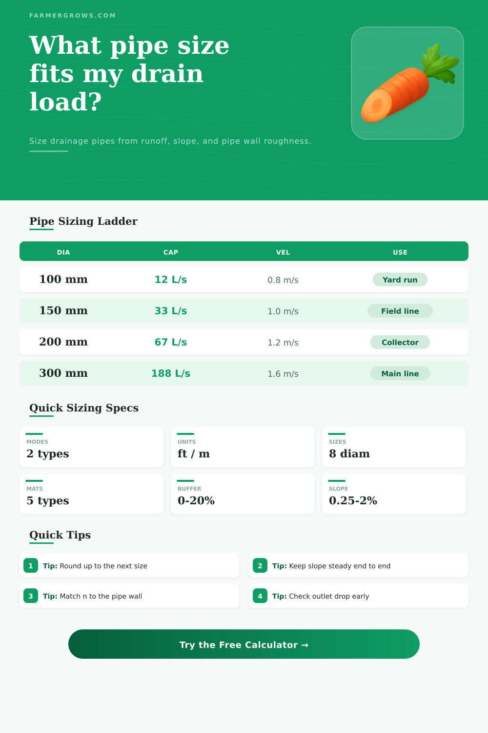
The ladder updates against the chosen slope and pipe wall, so you can see which diameters pass and which are too small.
| Nominal | Capacity | Velocity | Check |
|---|
| Surface | C value | Use case | Note |
|---|---|---|---|
| Roof | 0.95 | Downspout load | Fast runoff |
| Paved pad | 0.90 | Wash area | Little soak |
| Compacted lane | 0.75 | Drive track | Some loss |
| Crop field | 0.55 | Row drainage | Moderate flow |
| Pasture | 0.35 | Low runoff | More infiltration |
| Slope | Fall / 100 | Fall / 30 | Pipe note |
|---|---|---|---|
| 0.25% | 3.0 in | 75 mm | Very flat run |
| 0.50% | 6.0 in | 150 mm | Common target |
| 1.00% | 12.0 in | 300 mm | Steeper line |
| 2.00% | 24.0 in | 600 mm | Fast drainage |
| Nominal | 0.5% cap | 1.0% cap | Typical use |
|---|---|---|---|
| 4 in / 100 mm | 0.11 cfs / 3.2 L/s | 0.16 cfs / 4.5 L/s | Short lateral |
| 6 in / 150 mm | 0.33 cfs / 9.4 L/s | 0.47 cfs / 13.3 L/s | Small field run |
| 8 in / 200 mm | 0.78 cfs / 22.1 L/s | 1.10 cfs / 31.1 L/s | Collector branch |
| 12 in / 300 mm | 2.40 cfs / 68.0 L/s | 3.39 cfs / 96.1 L/s | Main drain |
Choose the next larger diameter when the margin is tight or the outlet may carry silt.
If your slope is flat, a smoother wall can buy you more capacity than a bigger trench.
In order to design a drainage system for the farm, it is necesary to calculate the size of the pipe that will be used to move the water that comes from heavy rain event. When it rains, water accumulate on the land and becomes what is referred to as “runoff”; the water that flows over the lands surface due to the inability of the ground to absorb the water quick enough to drain it. The amount of that runoff that passes through the drainage system will be the “peak” amount of that runoff, and is the maximum amount of water that will pass through the system during the heaviest parts of the storm.
The amount of peak runoff that will enter the pipe can be calculated from two factors: the amount of surface area that contributes to the area that will feed into the pipe, and the intensity of the rainfall during those peak periods. For instance, the rain that falls onto a gravel lane will produce more immediate runoff than if that same amount of rain fell onto a pasture; gravel is a less absorbent substance than grass. Similarly, a heavy storm that lasts for a short period of time will produce more immediate runoff than a long period of light rain; charts that depict the rainfall intensity for each region can be used to calculate the intensity of the rainfall that should be factored into the calculation of the necesary size of the pipe.
How to Size a Farm Drainage Pipe
The amount of surface area, the type of surface, and the rainfall intensity can all be combined to calculate the amount of peak runoff that will enter the pipe. The capacity of the pipe will depend upon three factor: the diameter of the pipe, the slope of the pipe, and the texture of the walls of the pipe. The diameter of the pipe will affect the amount of water that passes through the system; the larger the diameter, the more water can pass through the pipe.
However, a larger diameter of the pipe will require digging a larger trench. The slope of the pipe will impact the rate at which the water moves through the pipe; if the slope is too gentle, the water will move too slow, allowing silt and other particles to settle within the pipe; if the slope is too steep, the water will move too fast, potentially eroding the land at the outlet of the pipe. Finally, the texture of the walls of the pipe will impact the amount of friction that the water encounters as it move through the pipe.
Smooth pipes, like PVC pipes, will allow more water to move through them than corrugated pipes, whose ridges on the pipe walls create friction for the moving water. In order to calculate the amount of water that will enter the pipe, it is also necessary to calculate the runoff coefficient for each type of surface on the farm that may contribute to the water that enters the pipe. Runoff coefficients indicate the percentage of the rain that falls on a given area that becomes runoff.
For instance, the runoff coefficients for areas that contain roofs will be high, as most of the rain that lands on a roof will become runoff, while the runoff coefficients for areas with pastures will be low, as the grass and the ground will absorb the majority of the rain that falls on those area. Calculating the runoff coefficient for each area that will contribute to the drain pipe allows the designer of the drainage system to calculate the total amount of runoff that will enter the pipe. A buffer of 10 or 20 percent can be added to that calculation to account for any additional silt or rainfall.
It is also important to ensure that the pipe slopes steadily from the area to be drained to the outlet of the pipe. Sags within the pipe may cause the water to become trapped within the pipe, leading the system to overflow its designated area. The designer must also check the outlet of the pipe to ensure that the water can properly exit the pipe and enter the ditch.
If the outlet of the pipe is blocked or if the water level within the ditch is the same than the outlet of the pipe, the drainage system will not function correctly; the water will remain within the pipe. Finally, any pipe that is installed will need to be rounded up to the next available size. For instance, if calculations indicate that a six-inch pipe may be the size of the pipe that is needed to efficient drain the water from the farm, an eight-inch pipe should be selected.
Using a larger diameter pipe provides some margin for error in the system; the soil may change in the future, more water may run off of the farm than expected, and the larger pipe will still be able to handle those increased amount of runoff. Thus, if designed correctly, including calculating the proper size of the pipe and providing it with the proper slope, the drainage system will efficiently remove the water from the farm’s ground.