Drainage Tile Calculator
Estimate spacing, flow, tile length, and reserve capacity for farm fields, wet corners, and field drains before you lay tile.
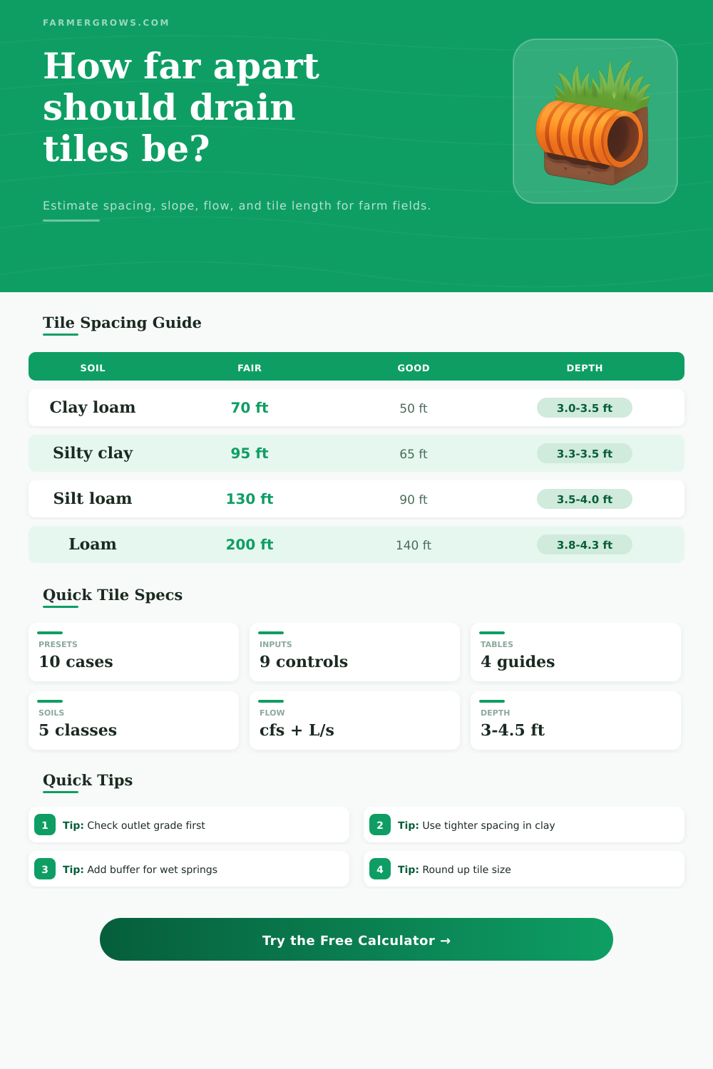
Use this quick visual grid to compare extension spacing baselines before you trust the auto result.
Sandy loam reaches 300 / 210 / 150 ft in the full table below.
Pick a field case to fill the inputs, switch units, and recalculate with a realistic starting point.
Laterals are assumed to run along field length, with the mainline crossing the width. The tile count and length update from that layout.
Drainage Tile Results
Enter field dimensions and soil details to see the recommended spacing, design flow, tile capacity, and reserve margin.
Calculation Breakdown
Use these quick guides to compare spacing, slope, flow, and drainage targets before you finalize the layout.
| Soil | 1/4 in/d | 3/8 in/d | 1/2 in/d |
|---|---|---|---|
| Clay loam | 70 ft | 50 ft | 35 ft |
| Silty clay loam | 95 ft | 65 ft | 45 ft |
| Silt loam | 130 ft | 90 ft | 60 ft |
| Loam | 200 ft | 140 ft | 95 ft |
| Sandy loam | 300 ft | 210 ft | 150 ft |
| Dia | Smooth | CPE | Silt risk |
|---|---|---|---|
| 3 in | 0.08% | 0.10% | 0.60 / 0.81% |
| 4 in | 0.05% | 0.07% | 0.41 / 0.55% |
| 5 in | 0.04% | 0.05% | 0.30 / 0.41% |
| 6 in | 0.03% | 0.04% | 0.24 / 0.32% |
| 8-12 in | -- | 0.07% | -- / -- |
| 12+ in | -- | 0.05% | -- / -- |
| Dia | 0.25% | 0.50% | 1.00% |
|---|---|---|---|
| 4 in | 0.07 cfs | 0.10 cfs | 0.14 cfs |
| 6 in | 0.20 cfs | 0.29 cfs | 0.41 cfs |
| 8 in | 0.44 cfs | 0.62 cfs | 0.88 cfs |
| 10 in | 0.80 cfs | 1.13 cfs | 1.60 cfs |
| 12 in | 1.30 cfs | 1.84 cfs | 2.60 cfs |
| Coeff | Cfs / acre | L/s / ha | Use |
|---|---|---|---|
| 0.25 | 0.0105 | 0.73 | Fair |
| 0.375 | 0.0158 | 1.10 | Good |
| 0.50 | 0.0210 | 1.47 | Excellent |
| 0.75 | 0.0315 | 2.20 | High need |
These tables use extension spacing baselines, minimum grade guidance, and Manning flow references. Local soils, outlets, and survey data still control the final layout.
Check the outlet first, because slope limits often decide the final tile size.
Use tighter spacing in clay, then widen only after the field drains well.
Tile drainage involve the use of buried perforated pipes to remove excess water from soils. Fields with poor drainage often has excess water in the soil that prevents the crop roots from breathing and for farm equipment to travel across the field. The use of buried perforated pipes in tile drainage systems help to remove the excess water from the soil profiles, allowing the soil to dry out.
In planning the installation of tile drainage, you must determine the layout of the pipes, the spacing of the lateral pipes, and the size of the mainline pipes. The first factor to consider in planning tile drainage is the type of soil in which the pipes will be installed. Soils that hold onto water, such as clay loams, will require the pipes to be installed closer together than sandy loam soils that allow water to drain more quick from the soil profiles.
How to Plan Tile Drainage
The depth at which the tile drainage system is installed is also a factor in the installation process. Different soil types requires different drainage goals to be set up for those fields. For example, fields that grow corn may require the drainage of half an inch of water per day, but fields that grow pasture grass may require less water drainage.
The shape of the field will dictate the amount of lateral pipe that will need to be installed. Fields that are narrow in width will require more lateral installation than fields with a more square field shape. The slope at which the tile drainage pipes are installed will also have an impact on the capacity of the system.
The diameter of the pipes, the type of the materials out of which the tiles are constructed, and the slope of the land can determine the capacity of the drainage tiles. For example, smooth pipes will allow for the movement of water easyer than corrugated plastic pipes. Furthermore, the drainage system must be able to handle the volume of water that fall during peak storms.
However, there should also be a buffer that allows for the system to be able to handle more water than is normal during a wet month on the farm. Sediment is one of the potential problem of installing tile drainage systems. For instance, fine soil particles can enter the drainage system and lead to clogging of the drainage system openings in the pipes.
If such is the case with the soil profile in which the drainage system will be installed, then the slope of the field can be steeper to ensure that the water does not have time to settle in the pipes. Coarser soils tend to be more stable and require gentler slopes in their pipe installation plans. Furthermore, there should be a buffer established in the drainage system in preparation for the extra water that may fall during heavy rains.
The use of presets allows for the farmers to quickly create a drainage plan for fields of different soil types. The presets use data collected from extension guidelines to determine the different dimensions and soil types of fields that will receive these drainage systems. For instance, a preset might be created for fields of clay loam soil that grow corn crops.
However, there will also be the ability to make manual changes to those presets in case there are areas of the field that contain more water than other area of the farm. A breakdown of the drainage plan will show the number of lateral installation pipes, the footage of the lateral pipes, and the slopes of the installation plan. Reference tables are also implemented into the preparation of the drainage plan.
Reference tables include tables that show the baselines of proven successful drainage systems. For instance, spacing grids can tell the farmer how far apart the drainage system lateral pipes should be installed based on the soil type and the drainage goals for that field. Another reference table can be used to determine the slope of the drainage system to prevent the setup of the system with the potential for undersized drainage pipes.
Finally, the capacity lookup table can ensure that a specific size for mainline pipes, such as 6-inch mainline pipes, will be able to handle the amount of water that the lateral field will drain. Common mistake should be avoided when installing tile drainage systems. One of the most common mistakes is to space the pipes too far apart to save money on the purchase of lateral pipes.
However, this will prevent parts of the field that are not covered by the laterals from being drained of excess water. Forgetting to also install the mainline pipe across the field will also significantly increase the cost of the drainage system. The outlet of the drainage system is another critical component of the installation of the system.
If the slope to the ditch where the water will be deposited is too steep, it will prevent the proper functioning of the tile drainage system. In this case, a survey of the field should be made prior to installing the tile drainage system to ensure that such a mistake will not be made. Furthermore, another mistake that should be avoided is failing to include a buffer into the installation plan.
Drainage systems will be established according to the rainfall that occur under normal conditions for the region. However, historical data about rainfall in these fields indicates that the drainage system may need to be oversized to accommodate for wetter than average spring. Aside from the benefits of including tile drainage systems on farms, there are other benefits of their installation.
These drainage systems can increase crop yield by 20 to 30 bushels of crops per acre on fields whose soil is otherwise marginal for the growth of those specific crops. Furthermore, because these drainage systems help to control water in the soil, there is an ability to install no-till farming and cover crop systems on these fields. Finally, farmers can also install these drainage systems on old clay tile systems by retrofitting the clay tiles with plastic pipes.
Depending on the budget for installation, farmers have a variety of options for the materials for the drainage system. For instance, drainage tiles that are constructed of concrete are more durable and helpful for fields with rocks in the soil. However, corrugated plastic tiles are also an option for these system.