Wind Turbine Spacing Calculator
Plan turbine rows from rotor diameter, downwind spacing, crosswind spacing, wake loss, land shape, and setback buffer before you stake a wind energy layout.
📋Layout presets
Choose a starting layout, then adjust the row count, D spacing, wake loss, shape, and setbacks for your site.
⚙Turbine spacing inputs
Wind array spacing results
Results update automatically as you edit the layout.
🗺Layout comparison grid
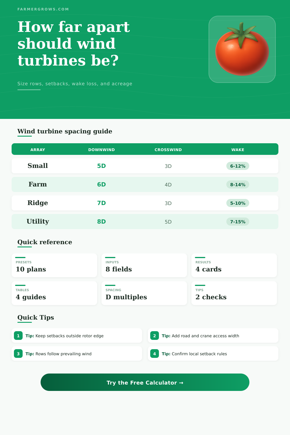
Compare tighter and wider spacing against your selected layout. Wider downwind spacing usually lowers wake loss but increases acreage.
📐Spacing and acreage formulas
| Item | Formula | Meaning |
|---|---|---|
| 1D | Rotor diameter | Base spacing unit |
| Downwind gap | D x downwind multiple | Row-to-row distance |
| Crosswind gap | D x crosswind multiple | Turbine-to-turbine distance |
| Acreage | Adjusted sq ft / 43,560 | Land footprint |
| Use case | Downwind | Crosswind | Note |
|---|---|---|---|
| Compact test | 4D-5D | 2.5D-3D | Higher wake |
| Farm field | 6D-7D | 3D-4D | Common start |
| Low wake | 8D-10D | 4D-5D | More acreage |
| Ridge line | 7D-9D | 2D-3D | Long strip |
| Shape | Factor | How applied | Best fit |
|---|---|---|---|
| Rectangle | 1.00 | Grid box | Open fields |
| Square | Square side | Max side squared | Equal leases |
| Ridge strip | 1.12 | Extra access | Long ridges |
| Irregular | 1.25 | Lease buffer | Odd parcels |
| Check | Typical | Calculator use | Why it matters |
|---|---|---|---|
| Wake loss | 5%-15% | Input percent | Energy loss |
| Outer setback | 500-1500 ft | Added both sides | Boundary clear |
| Access roads | 30-60 ft | Add to buffer | Crane access |
| Micrositing | Site study | Refine later | Wind resource |
Use the setback buffer for property lines, roads, dwellings, wetlands, and construction access. If a rule is based on turbine height, enter the larger value.
Keep downwind rows generous when the wind rose is narrow and strong. If winds are mixed, compare the selected layout with wider crosswind spacing.
This calculator is a planning estimator. Final turbine placement should use local code, geotechnical review, topography, utility interconnection, noise limits, and wind resource modeling.
Wind Turbine Spacing
Wind turbine spacing are a crucial factor in the design of a wind farm. The spacing between the wind turbine will determine how much energy the wind farm will produce. If the turbines is too close to each other, they will steal the wind from one another, leading to a reduction in the energy that they produce.
This reduction in energy production is known as wake loss. Therefore, the developers have to calculate the distance between the wind turbines to minimize this loss of energy production. The distance between the wind turbines is often calculate in terms of the rotor diameter of the turbines.
How Far Apart Wind Turbines Should Be
The rotor diameter is the distance from one blade tip of a turbine to the other blade tip when the turbine is not rotate. The rules for the spacing between the turbines is usually written as a multiple of the rotor diameter. For instance, if the rotor diameter of the wind turbines is 390 feet, a distance of 7D would mean that the distance between the rows of the turbines is 2,730 feet (7 times 390 feet).
The rotor diameter can be used to calculate the distance between the rows of the wind turbines and to ensure that the wind turbines are not too close to one another. The main reason why the developers must calculate the distance between the rows of the wind turbines is due to the phenomenon of wake loss. The wind does not travel in straight columns from one area to the next.
When the wind pass through a turbine, the wind becomes slower and more turbulent. This slower and more turbulent wind forms a cone of poor air quality that travel from the turbine. If another turbine is located within this cone of poor quality air, it will produce less energy then if it was exposed to the wind moving at a normal rate.
Additionally, due to the poor quality of this air, the second turbine will experience more mechanical stress on its component. Therefore, increasing the distance between rows of turbines will help to decrease the amount of wake loss that the turbines experience, though at the cost of increasing the amount of land that is required for the wind farm. There are two main types of spacing for the wind turbines within a wind farm.
These are downwind spacing and crosswind spacing. Downwind spacing is the distance between one row of wind turbines and the next row of wind turbines. Crosswind spacing is the distance between the turbines that are standing side-by-side within the same row.
The crosswind spacing between the turbines is important to ensure that there is enough room for the maintenance crews to work on the turbines. It is also important to prevent the turbine blade from overlapping in the path of the wind. The crosswind spacing is usually less than the downwind spacing since the wind usually travels between the turbines rather than through them.
However, any increase in the spacing between the turbines increase the total footprint of the wind farm, the area that is covered by the turbines, and the area that has to be leased or purchased by the wind farm developer. The shape of the land on which the wind farm will be constructed can also impact the placement of the wind turbines. Rectangular plot of land are the easiest to use in the construction of a wind farm.
However, plots of land of any other shape are more difficult to use due to access difficulties to some of the turbines, among other reasons. The shape factor in the wind farm area calculator can be used to adjust the area of the land that will be used for the construction of the wind farm. The shape factor will reflect the impact that the shape of the land have on the usable area within that land for the construction of the farm.
Additionally, another consideration for the developers is the setback distance for the farm. This setback distance must provide room for the roads, homes, wetlands, and to limit the noise that is created by the farm. The setback distance for the farm varies from location to location, so each wind farm will have to account for the specific requirement of the local county or utility.
There are calculators that can be used to compare the different spacing layout for the wind farm. For example, if the developers choose a layout that has the turbines closer together, they will save land for the farm. However, they will have to deal with the increased wake loss that is caused by the close proximity of the turbines.
Alternatively, choosing a layout that has more spacing between the turbines will lead to a reduction in the wake loss for the turbines, but the land required for the farm will increase. Neither layout for the turbines is better then the other, though. The choice between the two is determined by the cost of the land and the value of the electricity that will be produce by the turbines.
For example, if the land upon which the wind farm will be constructed is very cheap and inexpensive to purchase, choosing a layout for the turbines that create more electricity will be chosen. However, if the land is very expensive, the developers will likely choose a closer layout between the turbines to minimize the footprint of the farm on that land. Though the initial calculations for the spacing between the turbines will provide a general estimate for that distance, the positions of the turbines will have to change during the development of the wind farm.
Various study will be performed on the land to determine the final positions of the turbines. Though the final positions of the turbines will change from the initial calculations, the initial calculations are an important part of the development process to ensure that the layout of the turbines will not encounter any impossibilities during construction. Furthermore, the initial spacing calculations will ensure that the economic life of the turbines will be protected, as they will produce enough energy to meet the financial goal of the developers that own the turbines.