PWM Nozzle Calculator
Estimate pulsed nozzle flow, boom output, and application rate from duty cycle, pressure, spacing, and travel speed.
PWM Nozzle Results
Values update from the current duty cycle and pressure settings.
| Item | Value | Notes |
|---|---|---|
| Nozzle family | -- | Preset or custom nozzle |
| Base flow at reference pressure | -- | Selected nozzle rating |
| Pressure correction factor | -- | Square root of pressure ratio |
| Flow before PWM | -- | Open nozzle flow at operating pressure |
| Duty cycle factor | -- | Duty / 100 |
| Cycle period | -- | 1 / frequency |
| Open time | -- | Milliseconds per cycle |
| Closed time | -- | Milliseconds per cycle |
| Boom width | -- | Nozzle count x spacing |
| Total boom flow | -- | All nozzles combined |
| Travel speed | -- | Used for application rate |
| Target duty needed | -- | Only when target rate is entered |
| Duty | Flow Multiplier | Open at 12 Hz | Open at 20 Hz |
|---|---|---|---|
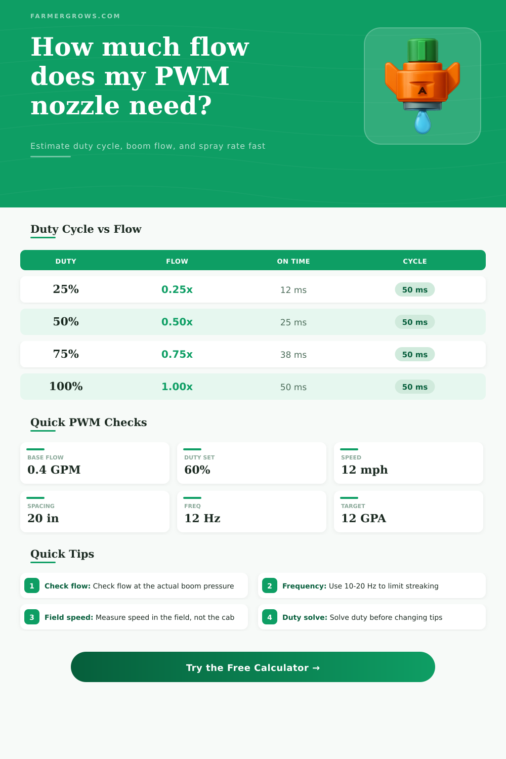
| 25% | 0.25x | 21 ms | 12.5 ms |
| 50% | 0.50x | 42 ms | 25 ms |
| 75% | 0.75x | 62 ms | 37.5 ms |
| 100% | 1.00x | 83 ms | 50 ms |
| Nozzle | Base Flow @40 PSI | L/min | Typical Use |
|---|---|---|---|
| 110-02 | 0.2 GPM | 0.76 | Low rate |
| 110-03 | 0.3 GPM | 1.14 | Standard rate |
| 110-04 | 0.4 GPM | 1.51 | Most booms |
| 110-05 | 0.5 GPM | 1.89 | Higher flow |
| 110-06 | 0.6 GPM | 2.27 | Heavy output |
| 110-08 | 0.8 GPM | 3.03 | Large output |
| AI 110-03 | 0.3 GPM | 1.14 | Drift control |
| AI 110-04 | 0.4 GPM | 1.51 | Lower drift |
| Speed | 0.3 GPM | 0.4 GPM | 0.5 GPM |
|---|---|---|---|
| 8 mph | 11.1 GPA | 14.8 GPA | 18.6 GPA |
| 12 mph | 7.4 GPA | 9.9 GPA | 12.4 GPA |
| 15 mph | 5.9 GPA | 7.9 GPA | 9.9 GPA |
| 20 mph | 4.5 GPA | 5.9 GPA | 7.5 GPA |
Pulse width modulation (PWM) is a method of control the flow of liquid through a nozzles of a sprayer. PWM systems uses solenoid valves to open and close the nozzles rapid. These solenoid valves allow the operator to control the output of the liquid from the nozzles electronically.
The term “pulse width” refer to the length of time that the solenoid valve is open. The length of time that the valve is open is expressed as a percentage of the duty cycle. For example, if the duty cycle is set to fifty percent, the solenoid valve will be open fifty percent of the time and be closed for other fifty percent of the time.
How PWM Controls Spray Flow
If the duty cycle is set to a high percentage, the PWM system will output a high flow of liquid from the nozzles. If the duty cycle is set to a low percentage, the PWM system will output a low flow of liquid from the nozzles. Because the PWM system control the duty cycle, the nozzles will maintain a steady pressure output even if the ground speed of the sprayer changes.
Another variable to consider in the PWM system is the ground speed of the sprayer. If the ground speed increase, more liquid must be released from the nozzles to provide the same application rate. However, if the ground speed increase but the liquid flow from the nozzles does not increase, the application rate will decrease.
The person that operates the sprayer must calculate the correct duty cycle in response to changes in ground speed to ensure that the application rate remain consistent. Consistent application rates of the liquid to the field will ensure that the liquid is distributed even across the field. Another variable that affects the flow of liquid from the nozzles is the pressure.
The flow of liquid through the nozzles is dependent upon the operating pressure of the system. If the operating pressure is higher than the rated pressure of the nozzles, more liquid will flow out of the nozzles. If the operating pressure is lower than the rated pressure of the nozzles, less liquid will flow out of the nozzles.
Because the flow of liquid from the nozzles change with the operating pressure of the system, changes to the operating pressure will affect the PWM systems calculated duty cycle. A third variable that can impact the PWM system is the frequency. Frequency is the number of times that the solenoid valves open and close in a period of one second, or in hertz.
If the frequency of the PWM system is too low, the nozzles may create streaking in the field. If the pulses of the solenoid valves are too low in frequency, the liquid will not be distributed as even as when the frequency is higher. If the frequency is too high, however, the valves will wear out more rapid.
Thus, it is necessary to find the frequency that provide even distribution of the liquid without causing rapid wear and tear of the solenoid valves. In order to operate the PWM system effectively, a person must use accurate measurement. Flow meters or catch cans can be use to measure the flow of the liquid from the nozzles.
These instruments will prevent incorrect readings from the speedometer and pressure gaages of the sprayer. For example, the sprayers speedometer may display a higher speed than the sprayer is actualy travelling if the sprayer is on a slope. Additionally, the PWM system will need to be calibrated each time that the nozzles of the sprayer are changed or when the pump setting are changed.
Each new set of nozzles will change the flow of the system, so the duty cycle will have to be recalculated. The major advantage of using a PWM system is that the ground speed of the sprayer and the application rate of the liquid are decoupled. This means that changes to the ground speed will not impact the application rate of the liquid.
Thus, the sprayer can travel at faster rates without impacting the amount of liquid distribute onto the field. Using a PWM system will save the sprayer fuel, since it is able to travel at higher rates of ground speed. Finally, the PWM system will help to maintain a steady droplet size of the liquid applied to the field, which will impact the efficacy of that liquid.