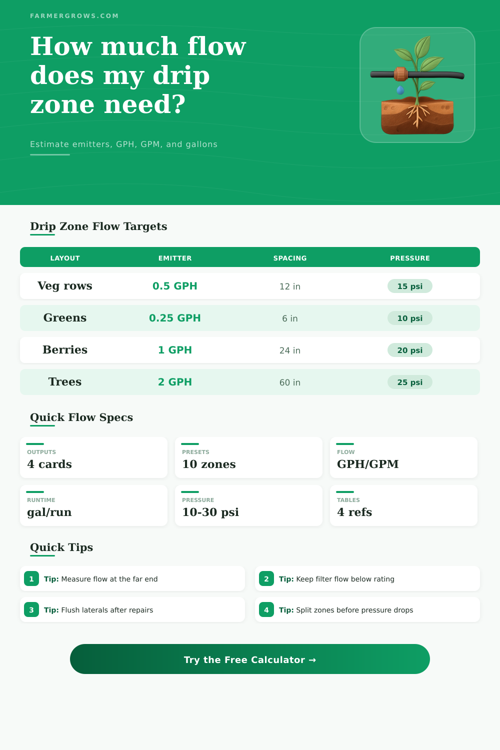
Drip Irrigation Flow Calculator
Size drip zone flow from emitter rating, spacing, row length, row count, pressure, lateral size, zone capacity, runtime, filter rating, and regulator setting.
Use the calculator to split drip irrigation into zones before installing tape, tubing, filters, regulators, or valves. Pressure-adjusted flow is an estimate; always confirm the finished zone with a catch test and a pressure gauge at the far end.
Drip Flow Results
Total flow is pressure-adjusted, then compared with zone capacity, lateral size, filter rating, and regulator setting.
| Flow step | Formula used | What it checks | Field note |
|---|---|---|---|
| Emitters per row | ceil(row length / spacing) | Outlets on each lateral | Round up so the far end gets an outlet |
| Total GPH | emitters x adjusted GPH | Whole zone water demand | Use this for pump, valve, and filter sizing |
| Total GPM | total GPH / 60 | Zone capacity comparison | Leave margin for dirty filters and elevation |
| Gallons per run | total GPM x minutes | Volume applied each irrigation | Useful for tanks, wells, and fertigation |
| Lateral size | Practical row flow | Typical row length | Best fit |
|---|---|---|---|
| 1/4 in microtube | 0.4 GPM | Up to 30 ft | Containers, short branches, individual pots |
| 1/2 in poly | 1.5 GPM | Up to 150 ft | Garden rows, small beds, berry lines |
| 5/8 in tape | 2.0 GPM | Up to 250 ft | Vegetable rows and market garden blocks |
| 3/4 in poly | 3.5 GPM | Up to 400 ft | Longer row blocks and orchard laterals |
| 1 in poly | 6.0 GPM | Up to 600 ft | Large zones or short submain laterals |
| Emitter rating | 100 emitters | 250 emitters | 500 emitters | Common use |
|---|---|---|---|---|
| 0.25 GPH | 25 GPH / 0.42 GPM | 62.5 GPH / 1.04 GPM | 125 GPH / 2.08 GPM | Dense tape, greens, seedlings |
| 0.50 GPH | 50 GPH / 0.83 GPM | 125 GPH / 2.08 GPM | 250 GPH / 4.17 GPM | Vegetables and raised beds |
| 1.00 GPH | 100 GPH / 1.67 GPM | 250 GPH / 4.17 GPM | 500 GPH / 8.33 GPM | Berries, vines, shrubs |
| 2.00 GPH | 200 GPH / 3.33 GPM | 500 GPH / 8.33 GPM | 1000 GPH / 16.67 GPM | Trees, bubblers, large containers |
| Filter or regulator item | Typical range | Calculator warning | Practical action |
|---|---|---|---|
| Screen filter | 120 to 200 mesh | Total GPM above filter rating | Upsize filter or split the zone |
| Disc filter | 120 to 155 mesh | High flow through dirty water | Clean often and watch pressure loss |
| Tape regulator | 10 to 15 psi | Pressure outside tape range | Match regulator to tape rating |
| Emitter regulator | 20 to 30 psi | Regulator differs from available pressure | Check gauge before and after regulator |
Before adding rows: Compare total zone GPM with filter rating, pump capacity, and valve size. A zone that looks fine by emitter count can still starve at the far end.
Before trusting pressure: Measure pressure while the zone is running. Static hose pressure is not the same as regulated pressure under drip flow.
Drip irrigation system designs requires a thorough understanding of water flow. Understanding water flow is more than simply turning on the water source. Before purchasing any irrigation equipment, its important to understand how much water will be delivered to each irrigation zone.
If the water that is delivered to the zone are too much for the filter to handle, the filter may become overwhelmed. Conversely, if the amount of water delivered to the zone is to little, the plants at the end of the irrigation zone may not recieve enough water. Thus, proper planning will ensure that the water is distributed even throughout each zone, and will ensure that the plants at the end of each zone are not starved of the water they requires.
How to Calculate Water Flow for a Drip Irrigation System
Understanding water flow in a drip irrigation system isnt a single measurement. Flow is related to the amount of water that is released from each emitter, the pressure at which the water exit each emitter, and the length of the laterals. If the amount of water that exits each emitter is changed, the pressure at which the water exits each emitter will change.
Additionally, if the pressure at which the water exits each emitter is changed, the total flow of water throughout the drip irrigation system will change. For example, drip irrigation tape may be designed to release well with fifteen pound per square inch of pressure. However, if an pressure regulator that reduces that pressure is used with the drip irrigation tape, the drip irrigation tape will push less water.
Additionally, if the drip irrigation tape is placed into a lateral line that is longer than the drip irrigation tape is designed for, the lateral line will lose pressure over such a length, reducing the amount of water that can travel down that lateral to the plants. The calculator located on this page allow one to determine the total flow of water that will be distributed throughout each irrigation zone. To use the calculator, one must enter the number of emitters, the spacing of those emitters, the length of the rows of plants, and the available pressure for the drip irrigation system.
Based off these inputs, the calculator can determine the total flow of water that will be distributed throughout each irrigation zone. The total flow can be compared to the capacity of the filter for that irrigation system, the size of the irrigation valve, and the flow limit of each lateral line. This comparison will indicate whether or not the irrigation zone will function proper when the pump is running and the filter begins to collect plant debris.
Each of the inputs that is required for the drip irrigation system calculator must be carefully entered into the calculator. For instance, the spacing at which the emitters are placed will determine how many emitter are placed on each lateral line. Each emitter on each lateral line will contribute to the total flow of that lateral line.
The rated pressure that is indicated on each emitter will not necessarily be the pressure that reaches the plants. The pressure that the plants receive will be less than the rated pressure due to the pressure regulator that is installed in the irrigation system. Additionally, the size of the lateral line is another critical input in the calculation of total flow.
Too small of a lateral line will result in a reduction of the lateral line pressure, and thus, a reduction of the flow of water that is distributed to the end of that lateral. In addition to the calculator, there are reference tables located below the calculator that can provide additional information regarding drip irrigation system design. The reference tables will allow those that use the calculator to quickly determine the flow of water (in gallons per minute) that will result with a certain number of emitters.
Additionally, the reference tables will tell the designer how much flow will pass through laterals of certain sizes, and how those laterals will change in flow based upon length. Furthermore, the reference tables will show the various pressure ranges during which certain types of emitters will effectively distribute water to the plants. When all of the variables are correctly accounted for, the drip irrigation system can be designed.
Based upon the calculations, a designer will know how many irrigation zones will be required, where the pressure regulators will need to be placed, and if the filter will be able to handle the total flow of water throughout the drip irrigation system. Thus, if the calculations are performed correctly, the drip irrigation system will function correctly for the entire growing season.