Field Tile Drainage Calculator
Estimate lateral footage, design drainage flow, full-pipe capacity, outlet reserve, and layout intensity for farm subsurface tile planning.
Use these results for planning conversations with a drainage contractor, engineer, NRCS office, or local drainage authority. Final tile size, outlet, permits, wetlands, utilities, and grade control need local verification.
Drainage Estimate
Results combine field geometry, selected tile spacing, drainage coefficient flow, and full-pipe Manning capacity at the grade entered.
| Soil type | Subsoil permeability | Fair 1/4 in/day | Good 3/8 in/day | Excellent 1/2 in/day | Typical drain depth |
|---|---|---|---|---|---|
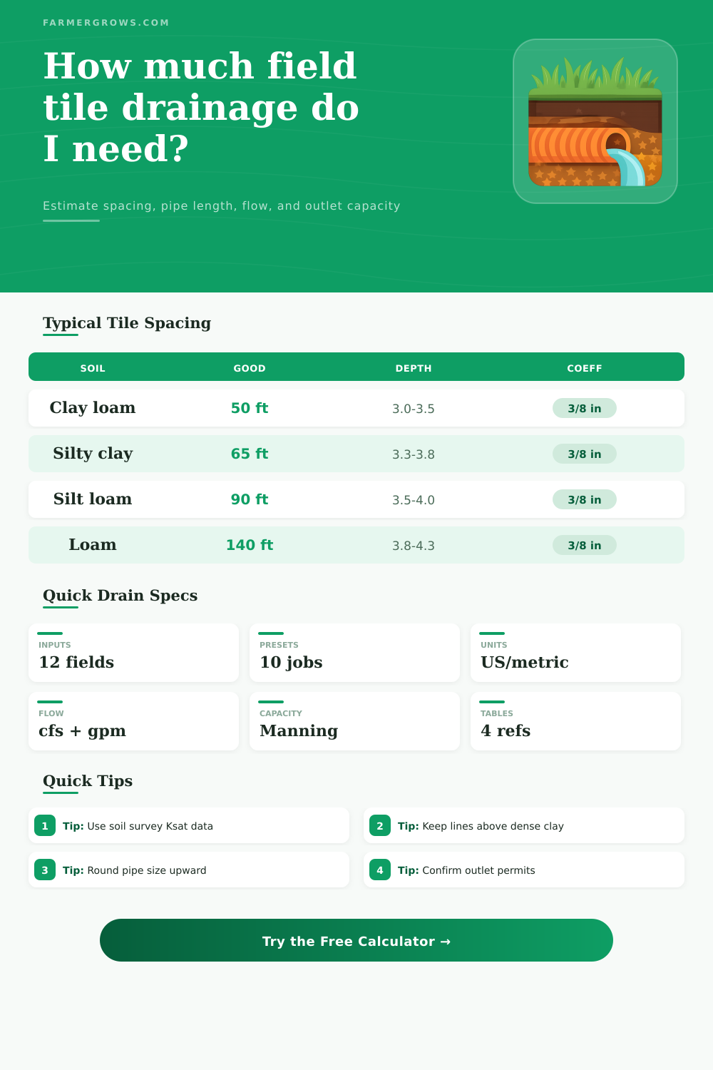
| Clay loam | Very low | 70 ft | 50 ft | 35 ft | 3.0 to 3.5 ft |
| Silty clay loam | Low | 95 ft | 65 ft | 45 ft | 3.3 to 3.8 ft |
| Silt loam | Moderately low | 130 ft | 90 ft | 60 ft | 3.5 to 4.0 ft |
| Loam | Moderate | 200 ft | 140 ft | 95 ft | 3.8 to 4.3 ft |
| Sandy loam | Moderately high | 300 ft | 210 ft | 150 ft | 4.0 to 4.5 ft |
| Coefficient | Metric equivalent | Water removed from 40 acres | Approx required flow | Typical use |
|---|---|---|---|---|
| 1/4 in/day | 6.4 mm/day | 10 acre-in/day | 0.42 cfs | Fair drainage or lower intensity pattern tile |
| 3/8 in/day | 9.5 mm/day | 15 acre-in/day | 0.63 cfs | Good row crop drainage target |
| 1/2 in/day | 12.7 mm/day | 20 acre-in/day | 0.84 cfs | Excellent drainage, closer laterals |
| 3/4 in/day | 19.1 mm/day | 30 acre-in/day | 1.26 cfs | Rapid drawdown or high-value crops |
| 1 in/day | 25.4 mm/day | 40 acre-in/day | 1.68 cfs | Very intensive systems needing strong outlet capacity |
| Planning group | Indicative saturated K | Drainage behavior | Spacing tendency | Field note |
|---|---|---|---|---|
| Very low permeability | Under 0.06 in/hr | Slow lateral movement | Closer spacing | Clay layers can limit effective depth. |
| Low permeability | 0.06 to 0.20 in/hr | Slow to moderate response | Close to moderate | Watch for stratified silty clay. |
| Moderately low | 0.20 to 0.60 in/hr | Reliable pattern response | Moderate spacing | Often suited to 60 to 100 ft rows. |
| Moderate | 0.60 to 2.00 in/hr | Faster lateral flow | Wider spacing | Grade and outlet may control design. |
| Moderately high | 2.00 to 6.00 in/hr | Rapid soil transmission | Widest spacing | Check sand stability and sediment risk. |
| Inside diameter | Minimum CPE grade without sand | Minimum CPE grade with fine sand | Acres at 0.10%, 3/8 in/day | Acres at 0.20%, 3/8 in/day |
|---|---|---|---|---|
| 4 in | 0.07% | 0.55% | 8.1 acres | 11.6 acres |
| 5 in | 0.05% | 0.41% | 15 acres | 20 acres |
| 6 in | 0.04% | 0.32% | 24 acres | 34 acres |
| 8 in | 0.07% | Site check | 49 acres | 69 acres |
| 10 in | 0.07% | Site check | 82 acres | 118 acres |
| 12 in | 0.05% | Site check | 127 acres | 180 acres |
| Field block | Area | Spacing | Estimated lateral ft | Common pipe role |
|---|---|---|---|---|
| 20 acre wet pocket | 20 acres | 40 ft | 21,780 ft | Pattern laterals to submain |
| 40 acre square | 40 acres | 50 ft | 34,848 ft | 4 in laterals, larger outlet |
| 80 acre half field | 80 acres | 60 ft | 58,080 ft | Multiple submains |
| 120 acre block | 120 acres | 80 ft | 65,340 ft | Staged main sizing |
| 160 acre section | 160 acres | 100 ft | 69,696 ft | Outlet capacity dominates |
Depth and spacing work together. Deeper laterals can influence a wider zone, but do not cut through a dense layer just to gain depth. A shallower line above the restrictive layer often drains more evenly.
Pipe size is usually outlet driven. A close pattern may remove water from the soil, but the main and outlet still have to carry the combined design flow without reverse grade or sediment problems.
Tile drainage involve placing pipe just below the soil’s surface. Field tile drainage determine how much water a field can hold or how much water a field can release after a period of rainfall. Field tile drainage will be designed in such a way that if the field drainage are correctly designed for that field’s soil and crop, then the field will reach an even drop in the water table levels, which will allow the crops’ roots to remain in the area where there is ample oxygen for the roots to breathe.
However, if the drop in the water table is created with too large a spacing between the drainage field tile or if the outlet for the field drain too slowly, then there will be wet pocket in the soil that will damage the crops that are grown in that field. The difference between a successful field drainage system compared to an unsuccessful one involves a variety of number, ratios, and calculations regarding that field and its drainage system. One of the first factor to consider in the creation of a field drainage system is the type of soil that is present in the field.
How to Plan Field Tile Drainage
Soils with low permeability will require drainage field tiles that are positioned closer to one another compared to fields with soils that have higher permeability. Clay loams will have lower rates of water movement through the soil compared to loams or sandy loam; hence, clay loams will require more closely spaced lateral pipe than sandy loams or loams. The second factor to consider is the depth at which the pipes will be place in the ground.
A field drainage pipe that is placed deeper into the soil will influence a larger zone of soil above the pipe. However, if that placed field drainage pipe encounter a layer of soil that restricts the movement of water in that soil layer, then the drainage pipe may not be able to effectively move the water from that field to the outlet. In this case, the decision must be made as to whether to place the drainage pipe into that layer of soil or to place it shallow into the field.
The drainage coefficient is the rate at which water is to be removed from the field, and it is expressed in inches per day. A drainage coefficient of 0.25 inches per day will be sufficient for fields with crops that are tolerant of high levels of moisture in their roots. A drainage coefficient of 0.25 inches per day will also be sufficient for fields that already have good surface drainage.
A drainage coefficient of 0.375 inches per day is typically targeted for fields with corn and soybean crops on soils within the Midwest. A drainage coefficient of 0.5 inches per day or more is useful for fields with high-value crops that need to be drain rapidly. Additionally, fields that will be ready for farm implements within a short span of time will also require a drainage coefficient that is set to a high number of inches per day.
If the drainage coefficient is increased from 0.375 inches per day to 0.5 inches per day, the outlet will need to be able to handle an additional one-third of the water movement that it will move at the higher rate. The third factor that must be considered is the drainage system layout pattern of the field. Drainage systems that use lateral field tile drains in parallel of one another will efficiently cover a field that is roughly in the shape of a square.
However, if the field is in the shape of a square, but there are different rate of drainage in each of the fields, then field drainage patterns that use herringbone pattern will best fulfill the needs of that field. Herringbone patterns will allow the water from the field to run into a central point, allowing the land to be drained in an efficient manner. Field patterns that use lines that are not in any specific layout or that an interceptor lines may be used for targeting specific areas of seepage in the field.
Additionally, interceptor lines may be used in targeting seeps or hillside seepage without having to treat the entire field with a field drainage system. Each of these field drainage layout patterns will require a small adjustment to the total footage of lateral field drainage pipes necessary for that field. These adjustments will be accounted for in the total order of the field drainage system indicated from the calculator.
Another factor to consider is the size of the field drainage pipes and the grade of the field. Manning’s equation will be used to calculate the flow of water through the field drains. The user will enter the diameter of the field drainage pipe and the slope of the field into the equation.
The equation will output a reserve percentage for that specific field and drainage system. Manning’s equation will calculate the amount of water that will move through the field drainage system at the determined rate. If that percentage is low, then it may be better to consider the use of a larger diameter field drainage pipe or a steeper field pipe grade.
Reference tables will be used to determine the flow of water through specific diameter of field drainage pipes so that there is accuracy in the measurements of those lateral pipes. Another factor to consider includes the field’s shape and the allowance for drainage connections. If the field is narrow and long, then there will be a greater amount of lateral pipe that will be placed into the field compared to a square field with the same area.
Additionally, some allowance for the field drainage pipes will need to be made for the main pipe, the connections between each of the laterally drained fields, and the number of cleanouts that will be installed into the system. These factors will have an impact upon the total amount of field drainage pipes that will be required. The next factor to consider is the capacity of the outlet.
The outlet can limit the amount of water that can be moved out of the field. For instance, if the outlet is a ditch that drains into a river, then the river may have limits to the amount of water that it can receive from the field. Additionally, other rules for that field and its outlet must also be considered.
These rules may impact the drainage field system layout that is created. These constraints exist outside of the field drainage calculator, but they will still dictate the drainage system that is created. It is essential for those using a field drainage system calculator to become aware of these constraints early in the calculation process.
Once the numbers have been determined for the field drainage system, the final step before implementing the system is to walk the field with an individual that has an understanding of how the water drain on the field throughout the year. While the calculator will provide the individual with an idea of the layout of the field drainage system, it is essential for the individual to ensure that the system will work in relation to the field and its outlet. Youll need to make sure the system is setup correctly to avoid any problems.
It is a bit more complicated than it looks but it should of worked out if you follow the steps.