Expansion Tank Sizing Calculator
Estimate thermal expansion volume, tank acceptance, cold precharge match, and pressure headroom for farmstead water heaters, hydronic loops, greenhouse heat, and rural pump systems.
Use this as a planning worksheet before selecting a listed tank. Final sizing should follow the tank maker, plumbing code, relief valve rating, antifreeze label, and the authority having jurisdiction.
Expansion tank estimate
Thermal expansion volume, pressure acceptance, and selected derating are combined into one tank size estimate.
| Fluid mix | Expansion coefficient | Expansion per 100 F rise | Typical rural use |
|---|---|---|---|
| Water, 0% glycol | 0.00023 per F | 2.3% volume growth | Domestic water, wash lines, open warm storage |
| 20% glycol | 0.00026 per F | 2.6% volume growth | Light freeze protection in utility rooms |
| 30% glycol | 0.00028 per F | 2.8% volume growth | Greenhouse and shop loops |
| 40% glycol | 0.00031 per F | 3.1% volume growth | Barn, orchard, and exposed hydronic piping |
| 50% glycol | 0.00034 per F | 3.4% volume growth | High freeze-risk closed loops |
| Pressure point | Common range | Used in calculator | Field note |
|---|---|---|---|
| Domestic static or fill | 30 to 70 psi | Cold baseline if no higher cut-out | Measure at the tank with the system cold. |
| Well pump cut-in | 20 to 50 psi | Reference only | Shows how low the pressure switch allows the system to fall. |
| Well pump cut-out | 40 to 80 psi | Cold operating pressure when higher than static | Thermal expansion often starts after pump shutoff. |
| Hydronic fill | 12 to 20 psi | Cold baseline for boiler loops | Raise only as needed for elevation and air removal. |
| Relief valve or design max | 30 to 150 psi | Upper pressure limit | Keep normal operation comfortably below relief lift. |
| Tank acceptance setup | Cold to max band | Approx acceptance | What changes it |
|---|---|---|---|
| Water heater, 50 psi precharge | 60 to 150 psi | 34% of tank volume | Higher pump cut-out lowers acceptance. |
| Water heater, 40 psi precharge | 50 to 150 psi | 36% of tank volume | Lower cold pressure leaves more gas room. |
| Boiler, 15 psi precharge | 15 to 30 psi | 34% of tank volume | Small pressure bands need larger tanks. |
| Glycol loop, 20 psi precharge | 20 to 45 psi | 46% of tank volume | Higher relief setting improves room. |
| Low precharge mismatch | 40 to 80 psi | often reduced | Too much cold water in the tank steals acceptance. |
| Water temperature case | Cold side | Hot side | Use this when |
|---|---|---|---|
| Shallow well heater | 50 to 60 F | 120 to 140 F | Typical home or cabin water heater planning. |
| Dairy or wash water | 45 to 55 F | 140 to 170 F | Washdown and sanitation can create a larger rise. |
| Radiant slab loop | 50 to 70 F | 110 to 140 F | Lower temperatures, but large loop volume matters. |
| Boiler or unit heater | 60 to 80 F | 160 to 190 F | Closed heating systems with smaller relief margins. |
| Solar preheat storage | 55 to 70 F | 160 to 200 F | Use conservative high temperature for stagnation risk. |
Precharge check: Set precharge with the water side depressurized, then match the cold fill or pump cut-out strategy recommended for the actual tank and system.
Relief caution: Do not use a tank calculation to justify operating at the relief valve edge. If the result is close, select the next listed tank size and verify the whole system.
When the water within the water heater or within the hydronic loop system heat up, the water within the loop expand due to the increase in the volume of the water with an increase in the temperature of the water. Within an open system, the expanded water will exit through the nearest faucet or hose bib. Within a closed rural system, however, the expanded water volume will encounter the system’s pipe, valves, and an pressure switch.
As a result of the water volume expansion within the system that encounters these components, the pressure within that system will rapidly climb. The expansion tank provide a place for that expanded water volume to go, which prevents the system relief valve from lifting and the water pump from tripping. The amount of expansion that occurs within a systems water are a function of the volume of the water, the expected rise in the water’s temperature, and the amount of glycol that is contained within the fluid.
Why Expansion Tanks Are Important in Closed Water Heating Systems
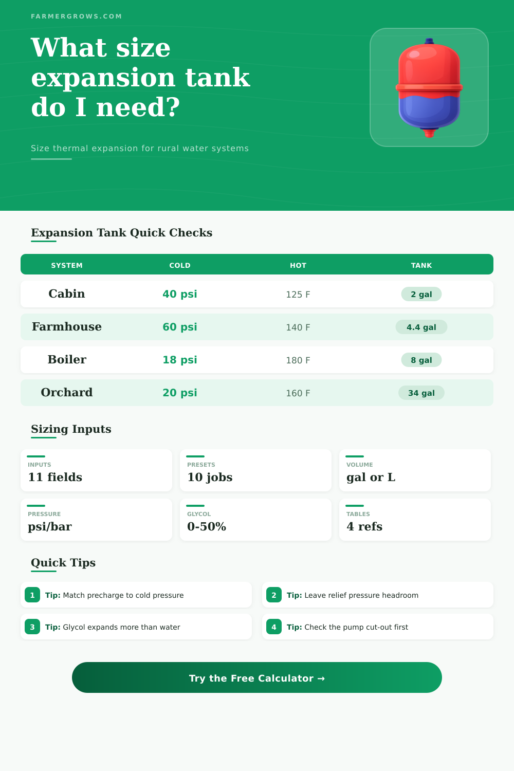
For instance, the cabin heater that use a shallow well has a fifty-degree rise in temperature in its fluid and almost no antifreeze; the greenhouse boiler loop, in contrast, has a rise in temperature of more than one hundred degrees with thirty percent glycol in the water. Consequently, each of these systems does experience expansion in its water, but the amount of water that expands are different within each system due to the different starting conditions for each of these systems. Calculators are available that will allow for the math to be performed to determine the amount of expansion within the system; using such a calculator will eliminate the need for the designer and installer to memorize the expansion coefficient for water.
In addition to the amount of expansion that the water experiences in a closed rural system, the behavior of the pressure within that system is also important to consider. Most expansion tanks operates on the principle of the gas laws. The air that is charged into the expansion tank will compress as the water enter the expansion tank.
The available space for the water within the expansion tank is a function of the gap between the operating pressure of the system when it is functioning normal and the setting of the system’s relief valve. For instance, a system that uses a well pump that stop at sixty psi but has a relief valve that is rated at one-fifty psi will have more space for expansion than a low-pressure boiler system whose pump stops at thirty psi. If the precharge pressure within the expansion tank is too far from the pressure of the system’s cold operation, the expansion tank will be partly filled with water; a partly filled expansion tank reduce the acceptance of the expansion tank.
A calculator is available that displays the relationship between the water pressure within the system and the acceptance of the expansion tank, which will allow the designer to decide if adjustments are to be made to the precharge pressure within the expansion tank or if changes are to be made in the size of that component. Additionally, the style of expansion tank that is manufactured also play a role in the outcome of the systems water expansion. For instance, steel compression tanks rely upon an air cushion to provide the expansion capacity for the system’s water; the air cushion will gradually lose its capacity as it absorbs the water from the system.
Diaphragm tanks and bladder tanks, in contrast, physically separate the water within the tank from the air within the tank; as a result, the acceptance for these tanks is more likely to remain in the calculated value for that system. A field acceptance factor can be used in the calculator to account for the age of the tank fittings and potential uncertainty in the acceptance calculations; using the field acceptance factor account for the uncertainty of the system when the pipes are buried or run through a wall. It is important to note that most systems will differ from those described due to the different patterns in which the temperatures of the systems’ fluids rises.
For instance, while the fluid within a dairy farm wash line system may reach higher temperature than a house heater system, the average temperature within the dairy system will be lower than the temperature of the system’s set point due to the cycling of those heaters on and off. Similarly, an orchard system that is used to protect plants from frost may remain idle for several weeks at a time, but will heat rapidly when the temperature drop to the levels that activate the system. Thus, within both the dairy and orchard systems, the pressure band into which the system operates and the mixing of the system’s fluids is more important than any single temperature measurement of the system.
Reference tables are available that show how the glycol concentration within the system affects the expansion coefficient, and tables are provided for showing the relationship between the pressure within the system and the rural system components. These tables can be used by the designer to determine if the size of the expansion tank calculated by the calculator is likely to be within a reasonable range for that system, and to understand the reason for the need for a larger expansion tank for a system with a small pressure band. For instance, the small pressure band that is established by a boiler system will require a larger expansion tank than a water heating system of the same volume.
After the designer calculates the size of the expansion tank, it is common and necessary to round up to the next size of listed expansion tank. In addition, the relief valve for that system should be rated to a pressure that is more higher than the normal operating pressure of the system. This step is critical as a means of protecting the system against other variables within the system, such as a clogged inlet for the system or a drifting pressure switch.
This step ensures that the system will remain within its operating limits, rather than reaching its relief valve every time that the burner within the system is fired.