PVC Pipe Buoyancy Calculator
Estimate whether an empty, partly full, buried, or anchored PVC line will float by comparing displaced water force against PVC wall weight, internal liquid, soil cover, ballast, and anchor spacing.
Use this calculator for farm drainage, pond intake, irrigation sleeves, greenhouse return lines, and shallow utility runs where buoyancy can lift PVC during flooding or high groundwater. Results are planning estimates; final restraints should be checked by a qualified designer for critical lines.
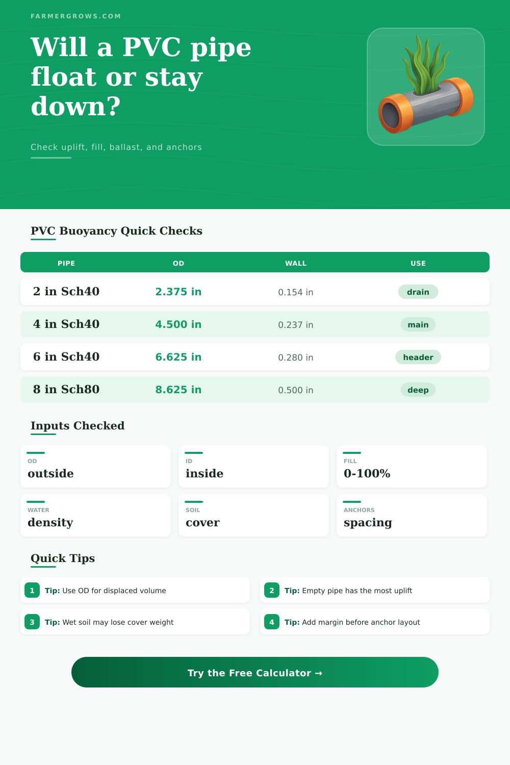
These quick cases show why large empty pipe is usually the worst buoyancy condition. PVC wall weight rises slowly compared with displaced water volume as diameter increases.
Buoyancy Results
The calculator uses displaced volume = outside cylinder volume, buoyant force = displaced volume x outside water density, pipe weight = PVC wall volume x PVC density, fluid weight = inside volume x fill fraction x fluid density, and net uplift = buoyant force x safety factor minus all downward resistance.
| Nominal pipe | OD (in) | ID (in) | Wall (in) | Estimated PVC weight |
|---|---|---|---|---|
| 2 in Schedule 40 | 2.375 | 2.067 | 0.154 | 0.72 lb/ft |
| 4 in Schedule 40 | 4.500 | 4.026 | 0.237 | 1.43 lb/ft |
| 6 in Schedule 40 | 6.625 | 6.065 | 0.280 | 2.31 lb/ft |
| 8 in Schedule 40 | 8.625 | 7.981 | 0.322 | 3.53 lb/ft |
| 8 in Schedule 80 | 8.625 | 7.625 | 0.500 | 5.38 lb/ft |
| Item | Formula used | Main input | Why it matters |
|---|---|---|---|
| Displaced volume | pi x (OD/24)^2 x length x submergence | Outside diameter | Only the outside envelope pushes water away. |
| Buoyant force | Displaced volume x outside water density | Water density | This is the upward force before safety factor. |
| PVC wall weight | Wall annulus volume x PVC density | OD, ID, density | Heavier wall schedules resist uplift. |
| Fluid weight | Inside volume x fill percent x fluid density | ID, fill, fluid | A full line may be close to neutral in water. |
| Net uplift | Buoyancy x safety factor minus downward resistance | Ballast, soil, anchors | Positive means more restraint is needed. |
| Internal condition | Typical density | Weight effect | Buoyancy note |
|---|---|---|---|
| Empty pipe or air | 0 to 0.08 lb/ft3 | Nearly no internal weight | Usually the worst uplift condition. |
| Fresh water | 62.4 lb/ft3 | Strong downward weight | Can nearly balance displacement inside the ID. |
| Nutrient solution | 63 to 68 lb/ft3 | Slightly heavier than water | Useful for greenhouse return or fertigation lines. |
| Slurry or sediment water | 70 to 90 lb/ft3 | Much heavier fill | May settle unevenly and should be checked separately. |
| Restraint item | Calculator input | Field check | Common caution |
|---|---|---|---|
| Concrete ballast | Added ballast total | Confirm submerged effective weight if fully underwater. | Dry weight may overstate the useful restraint. |
| Soil cover | Cover depth, width, density, saturation | Use realistic bearing width over the pipe. | Saturated loose soil gives limited uplift resistance. |
| Strap anchors | Spacing and capacity | Compare uplift per anchor with allowable load. | Hardware corrosion and soil pullout control capacity. |
| Closer spacing | Anchor spacing | Shorter spacing lowers load per anchor. | Pipe stress at the strap still needs a local check. |
Worst case: run the calculator with the pipe empty, fully submerged, and the soil saturation reduction high. That usually gives the conservative uplift condition for flooding or a dewatered line.
Anchor check: compare load per anchor with the allowable working capacity, not the ultimate pullout value. Include fittings, bends, and exposed pipe sections where uplift may concentrate.
When a PVC pipe lift out of a flooded trench or when a pond intake pipe move upward during a storm, there is an upward force at work. Water exert an upward force on any objects that it displaces, and the hollow PVC pipe will displace a significant amount of water. In order to calculate if the pipe will lift out of the ground, you must understand both the upward force of the water in the pipe and the downward force of the weight of the pipe.
The outside diameter of the PVC pipe will determine the size of the cylinder of water that are displaced by the pipe. Because a larger outside diameter will displace more water, the more larger the outside diameter of the PVC pipe, the larger the upward force that act upon the pipe. The inside diameter of the PVC pipe will determine the weight of the fluid that is contained within the pipe.
Will a Buried PVC Pipe Float Up?
An empty PVC pipe will have very little internal weight; empty PVC pipes are the most likely to experience upward movement. You can account for the weight of the fluid that is within the pipe by employing a fill percentage in the calculations. Small changes in the internal weight of the fluid will have a greater impact upon the upward movement of the pipe than many peoples may expect.
The soil that is covering the PVC pipe will contribute to the downward force upon the pipe. Only the unsaturated soil will provide an effective downward force upon the pipe, however saturated soil will lose some of that downward force due to the fact that the water will fill the pores within that soil. The calculation of the forces upon the pipe can account for the saturation reduction of the soil.
The width of the trench in which the pipe is being installed will also have an impact upon the downward force upon the pipe. Only the soil that bear upon the PVC pipe will contribute to that downward force. Ballast and anchors may be required to hold the pipe in place if the downward forces of the soil and fluid is not enough to provide for the holding power of the pipe.
Examples of ballast and anchors include concrete collars, concrete blocks, and screw anchors. The resistance provided by ballast and anchors does not depend upon soil condition. The closer the spacing between the anchors will be, the more force that each anchor must provide to hold the pipe in place.
Closer spacing between the anchors will require the use of more hardware to provide adequate holding power for the pipe. The use of a safety factor can help to ensure that the pipe will remain stable despite changes in the water table or the wetting of the soil. The calculator will perform the calculations after you enter the dimensions of the pipe and the conditions of the soil.
The calculator will compare the upward force of the water to the downward forces upon the pipe, and display whether or not the pipe will remain in place. Because of the presence of buoyancy force it is possible for a pipe to initially appear to remain in place when being installed, yet become lifted out of the ground some weeks later following a rise in the water table. In addition to the factors that are accounted for in the calculator, there are additional considerations for sites where PVC pipes is installed.
Fittings and bends in the pipe will affect the distribution of the uplift force upon the pipe. A change in the direction of a pipe may result in a concentration of the uplift force upon a specific portion of the pipe. The portions of the pipe that are exposed to water will experience different depths of water than those portions of the pipe that is buried within the ground.
These depth difference may become important during flooding events. Additionally, the expansion and contraction of the PVC pipe due to changes in temperature can loosen the straps that holds the pipe to the ground. It is recommended to perform a worst-case scenario check for PVC pipes.
The worst case scenario would involve an empty PVC pipe with high saturation reduction of the soil. By calculating this scenario first, one can ensure that the pipe layout will have some margin for error in the face of uplift forces. In the case that the pipe does exhibit uplift forces, one can decide whether additional ballast is required or whether the spacing between the anchors should be shortened.
Common mistakes in calculations may include only considering the downward force of the soil upon the pipe, or assuming that the forces upon an empty PVC pipe are similar to those upon a full PVC pipe. Soil saturation can reduce the downward forces upon the pipe, as can the pipe becoming empty of fluid. These two condition is something that should of been considered prior to burying the PVC pipe or attaching the straps to the pipe.
The reference tables provide information regarding the sizes of PVC pipes that are commonly used and the effect of different conditions within those pipes upon their overall weight. These tables are not to replace the calculation requirements of the calculations, but may help provide individuals with an idea of the expected weight of the PVC pipes prior to entering the numbers into the calculator. The reference tables indicate the force of the water that is within the pipe based off the outside diameter of the pipe, as well as the force of the fluid within the pipe based upon the inside diameter of the pipe.
These two force are the forces that are considered within the calculation of whether or not the pipe will remain in place. In addition to the calculations, individual judgment is required in the evaluation of the installation. The capacity of each anchor to provide force upon the pipe will depend upon the type of soil, depth below the surface, and type of corrosion protection.
Additionally, ballast blocks may settle over time if they is not placed upon stable material. Each of these factor can impact where inspection of the pipe at each point of restraint is required, particularly for large diameter pipes. These factors are in addition to the calculation and the holding power of the pipe.
By performing these calculations prior to backfilling the trench in which the PVC pipe is being installed, or prior to the first rain that falls in that area, it is possible to prevent any movement of that pipe. Additionally, by performing the buoyancy calculation prior to the installation of the pipe, it is also possible to prevent that pipe from lifting out of the ground.