Centrifugal Pump Curve Calculator
Build a three-point pump curve, scale it by impeller diameter and RPM, overlay a quadratic system curve, and estimate the operating point where pump head equals system head.
Use manufacturer curve data when available. This calculator interpolates between shutoff, BEP, and runout points; it does not replace vendor selection software, NPSH checks, motor checks, or field testing.
Operating Point Result
The solver searches the scaled pump curve and the system curve to find the flow where both heads are closest.
| Curve point | Meaning | Typical input | How calculator uses it |
|---|---|---|---|
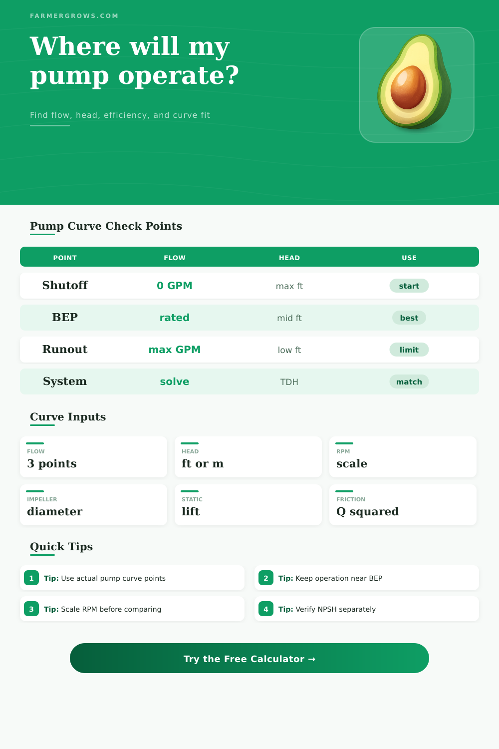
| Shutoff | Zero-flow head with discharge closed | 0 GPM, maximum head | Sets the left end of the pump curve. |
| BEP | Best efficiency point | Rated flow, rated head, efficiency | Anchors efficiency and the center curve segment. |
| Runout | Far-right high-flow limit | Maximum flow, lower head | Caps the search range and warns about overrun. |
| Operating point | Pump curve meets system curve | Solved value | Reports expected flow, TDH, efficiency, and power. |
| Change | Flow effect | Head effect | Power caution |
|---|---|---|---|
| RPM change | Flow follows RPM ratio | Head follows RPM ratio squared | Power rises about RPM ratio cubed. |
| Impeller trim | Flow follows diameter ratio | Head follows diameter ratio squared | Power usually falls with trim; verify curve. |
| RPM and diameter | Flow factor = RPM ratio x diameter ratio | Head factor = flow factor squared | Confirm motor load and pump limits. |
| Large changes | Approximation becomes weaker | Published curves are preferred | Use vendor data for final selection. |
| System part | Formula role | What raises it | Practical correction |
|---|---|---|---|
| Static head | Constant head at every flow | Elevation lift, pressure requirement | Lower tank height or pressure target when possible. |
| Friction head | Increases with flow squared | Small pipe, filters, valves, long runs | Use larger pipe, clean filters, reduce restrictions. |
| Reference flow | Defines K in static + KQ² | Wrong test point or mixed units | Use the same unit system for flow and head. |
| Intersection | Operating point | Shifted pump or system curve | Adjust RPM, impeller, piping, or operating zones. |
| Region | Flow vs BEP | Common symptom | Selection note |
|---|---|---|---|
| Left of curve | Below 70% of BEP | Heat, vibration, recirculation risk | Reduce head or use a smaller pump. |
| Preferred band | 70% to 120% of BEP | Stable, efficient operation | Usually the best target for irrigation duty. |
| Right of BEP | 120% to 140% of BEP | More motor load and lower efficiency | Check motor amps and minimum head. |
| Runout edge | Above 140% of BEP | Cavitation or overload risk | Throttle, resize pipe, or pick another pump. |
Plot the system before changing pumps. A larger pump may still miss the target if the real limit is pipe friction, clogged filtration, undersized suction piping, or excessive pressure head.
Keep the duty point near BEP. For continuous irrigation or greenhouse circulation, a point near the best efficiency region usually runs cooler, quieter, and more reliably.
Centrifugal pumps moves water by spinning an impeller inside the pump housing. Centrifugal pumps create a relationship between the flow of water from a pump and the pressure of that water that isnt a straight line. Most systems does not exist at one single pressure.
Changes in the elevation of a system, changes in the friction within a system, changes in filters and changes in valves can all contribute to a change in the resistance that the system presents to the pump. The relationship between a centrifugal pump and a system is represented as the location of the two curves crossing each other. The relationship between those two curves is essential to determining whether a pump will efficiently move the amount of water that is necessary for a system, whether the pump will overheat, whether the motor will be overloaded, and whether the system will experience vibration in operation.
Matching a Centrifugal Pump to a Water System
To define the pump side of the equation, three specific points from the published centrifugal pump curve is required. These three points are the shutoff head at zero flow, the best efficiency point, and the far right runout point of the pump curve. These three points allow the calculator to establish a line that represents the pump curve between the maximum head that the pump will generate and the maximum flow that the pump can push through the system.
The best efficiency point includes a percentage that expresses the efficiency of the pump at that point; the efficiency percentage represent the portion of the motors energy that reaches the water at that point on the centrifugal pump curve. Both the speed and the diameter of the impeller will change the pump curve; the affinity laws can be used to calculate how much those change will impact the pump curve. Flow is proportional to both the ratio of the motor speed to the impeller speed as well as the impeller diameter.
Head is proportional to the square of that same equation. Trimming the impeller or decreasing the motor speed will decrease the flow of water from the pump; the same adjustment to the impeller will also decrease the pressure of the water that exits the pump. On the system side of the equation, two main number are required.
These numbers are the static head of the system and the friction head of the system. Static head is a constant value for a system; static head does not change with the flow rate of water through that system. Friction head is not a constant within a system; friction head increases with the square of the flow rate of water through the system.
The friction coefficient is calculated at one flow rate and then applied to other flow rates within the system. Once the pump curve and system curve exist within the same units, the point of operation for that system can be found by finding the flow rate at which the head of the pump curve and the head of the system curve are the closest to each other. This point will contain information about the flow rate of the system, the efficiency of the pump at that flow rate, and the brake horsepower of the motor that drive that centrifugal pump.
Presidents of the American Society of Civil Engineers and other engineering notables has recommended that each engineer that designs a system that will include centrifugal pumps sizes the pumps according to a target flow rate and a target head. These engineers then select the next largest size pump model that is available in the centrifugal pump catalog. However, this method can fail if the actual system to which the pump will be applied is not similar to the system depicted in the engineering drawings.
If the system creates a steeper system curve than the engineering drawings would suggest, then the pump will be operating to the left of its best efficiency point. Centrifugal pumps that operate to the left of their best efficiency point will overheat and may even recirculate water within the pump casing. Alternatively, if the actual system to which the pump will be applied creates a flatter system curve than the engineering drawings would suggest, the pump will operate beyond the best efficiency point into the runout of the pump design.
Pumps that operate in their runout region will have low efficiency and will draw more current than the motor nameplate allow. These outcomes can be avoided if the target flow and head are within an acceptable range from the manufacturers specification. The reference tables are provided to describe the three-point centrifugal pump curve as an approximation.
Centrifugal pump curves that is published in manufacturer data are rarely perfectly straight between the three required points; those lines are approximations. Furthermore, the affinity laws are only approximations; they are most accurate within the speed and impeller diameter at which the pump was tested. The tables explain what each point on the pump curve represents.
Additionally, the tables explain the changes to those centrifugal pump curves if the rotational speed of the pump is changed, if the diameter of the impeller is changed, and if the suction condition and net positive suction head available to the pump are changed. Centrifugal pump curves and system curves can be compared in the design phase of engineering projects to determine what head and flow rates the pump requires to adequately supply the system with water. The efficiency at which a centrifugal pump operate at its point of operation will likely not be the same as the best efficiency of that pump.
The calculator will estimate the difference between those two efficiency rate by measuring the distance between the point of operation of the pump and the flow rate at which that pump produces the best efficiency. A point of operation that is at seventy percent of the flow rate that produces the best efficiency from the pump is likely acceptable for seasonal use of the pump. However, if the point of operation is at forty percent or one hundred forty percent of the best efficiency flow of the pump, then adjustments need to be made to the system in which the pump will be used.
Power is calculated as the product of the efficiency of the pump and the water horsepower that must be delivered to the system. The unit of this measurement is brake horsepower, which indicates whether the existing motor for the pump has an appropriate amount of margin for the system that must be supplied with water. The centrifugal pump calculator does not have the ability to see the actual conditions under which a pump will operate.
Cavitation within a pump can occur if the suction condition for a pump are not adequate. The temperature of the water that will be pumped will impact the viscosity of the water; different viscosity rates create different margin within which a pump can operate. Solids that are contained within the water will create additional wear on the impeller for that pump, and the solids will also create additional roughness within the inner cavity of the pump.
These variables will impact the friction coefficient within the pump over time; they will shift the actual operating point of that centrifugal pump. A person can avoid any unpleasant surprise with a centrifugal pump installation by calculating the system curve prior to selecting the centrifugal pump. The static head of a system is the highest static head that will be present within the system.
Additionally, the friction head at the target flow for that system is the friction head that will be created within the system. These two number should be determined prior to installing the pump; they are essential elements to calculating the system curve. The calculator will determine the remainder of the system curve once these two system variable are provided to it.
These calculations are essential for determining the flow, the efficiency of the pump, and the brake horsepower of the motor.