Water Pump Pipe Size Calculator
Choose a practical suction or discharge pipe size by checking flow, pipe length, allowable velocity, Hazen-Williams friction loss, fittings, elevation, and available pump head.
The calculator tests standard nominal pipe sizes. It first estimates the minimum inside diameter from velocity, then checks each pipe for friction pressure loss and total dynamic head.
Recommended Pipe Size
Results update after calculation.
These cards compare nearby nominal pipe sizes with the same flow, material, fittings, elevation, and pump head inputs.
| Step | Formula Used | Input Units | What It Checks |
|---|---|---|---|
| Velocity | v = 0.4085 x GPM / d^2 | GPM, d in inches | Water speed in ft/s |
| Velocity diameter | d = square root(0.4085 x GPM / v limit) | GPM, ft/s | Minimum ID from speed |
| Friction head | hf = 4.52 x L x Q^1.85 / (C^1.85 x d^4.87) | ft, GPM, C, inches | Hazen-Williams pipe loss |
| Total head | TDH = elevation + friction head | feet of water | Pump head required |
| Material | Typical C Factor | Inside Diameter Adjustment | Best Use |
|---|---|---|---|
| PVC / CPVC | 150 | Schedule 40 base ID | Irrigation discharge, clean water |
| HDPE irrigation pipe | 140 | About 95% of base ID | Buried farm and pasture runs |
| Black poly tubing | 135 | About 92% of base ID | Flexible garden and stock lines |
| Aluminum irrigation pipe | 130 | About 98% of base ID | Portable mainlines and laterals |
| Galvanized steel | 120 | About 96% of base ID | Durable exposed pump plumbing |
| Pipe Location | Typical Velocity Target | Pressure Loss Target | Why It Matters |
|---|---|---|---|
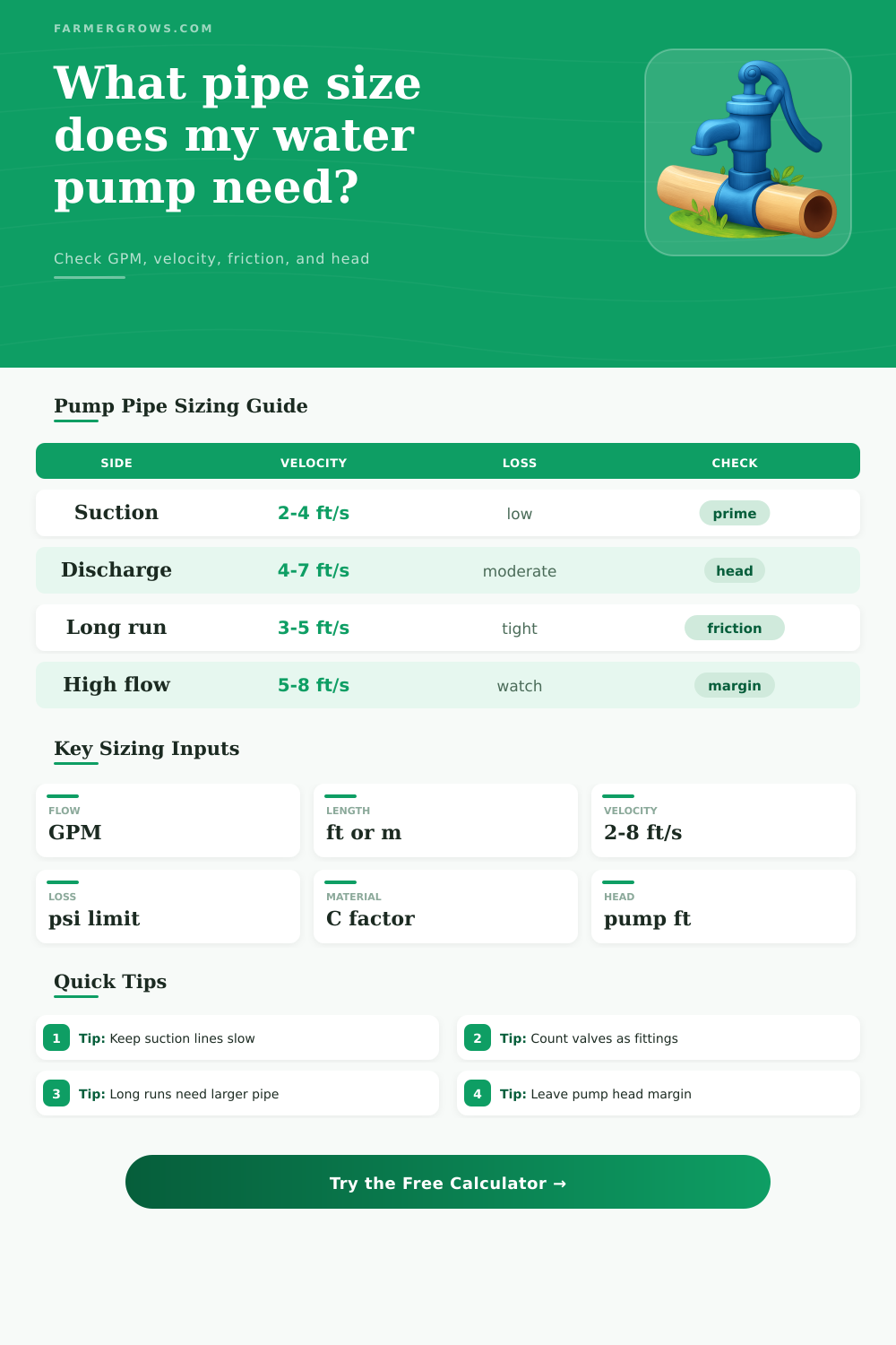
| Pump suction line | 2 to 4 ft/s | Very low, often 1 to 2 psi | Reduces priming trouble, cavitation risk, and intake noise |
| Discharge line | 4 to 7 ft/s | Often 3 to 8 psi | Balances pipe cost, pump head, and outlet performance |
| Long irrigation main | 3 to 5 ft/s | Keep total loss tight | Small friction changes become large over long distances |
| Short washdown hose | 6 to 8 ft/s | Higher loss acceptable | Short runs can tolerate faster water if pump head is ample |
| Nominal Pipe | Typical ID Used | Approx. Flow at 5 ft/s | Common Farm Use |
|---|---|---|---|
| 3/4 in | 0.824 in | 8 GPM | Small garden zones, short transfer lines |
| 1 in | 1.049 in | 13 GPM | Greenhouse benches, small pumps |
| 1-1/2 in | 1.610 in | 32 GPM | Stock tanks, pond circulation, washdown |
| 2 in | 2.067 in | 52 GPM | Orchard blocks and larger transfer pumps |
| 3 in | 3.068 in | 115 GPM | Mainlines, high-flow irrigation, long runs |
| 4 in | 4.026 in | 198 GPM | Large farm mains and pond supply headers |
Flow values are approximate because actual inside diameter changes with pipe material, wall thickness, and fittings.
When moving water through a system using a pump, the pipes must move the water without force the pump to work too hard or wasting energy. If the pipe is too small, the water will have to move quick through the pipe, increasing the friction between the water and the pipe walls, forcing the pump to work more harder than necessary. Using a pipe that is too large for the needs of the system will result in a customer pay for pipe that isnt being used effectively.
You must choose the size of the pipe such that the velocity, friction, and head are all in balance for the specific run of pipe that is to be installed. The flow rate of the system is one of the primary factors in determining the size of the pipe that will be used in the system. The flow rate that should be used to size the pipe is the working flow rate of the system, not the maximum flow rate of the pump.
How to Choose the Right Pipe Size for a Pump
Using the maximum flow rate will cause the pump to run slower than necessary most of the time but may result in a loss of head of the pump. Using an average flow rate may result in the flow of water being too restrictively in the system when there are high demands on the water. A calculator can determine the correct size of the pipe by entering the flow rate, length of the pipe, and the material from which the pipe will be made.
Using such a calculator allows people to avoid have to guess at the friction coefficients of the system. Another of the factors that must be considered is the length of the pipe. This is a factor that you will have to measure careful.
The distance from the pump to the intake or the other discharge point is the distance that will be measured. This distance will not necessarily be the same as the distance that is measured on a map; it could be much longer due to the need of the pipe to go around buildings or follow the slope of the land. Every additional foot of pipe will result in an additional loss of head of the pump.
For long runs of pipes, even a small difference between sizes can result in a very large difference in head loss. The length of the pipe will impact the friction loss in the system, meaning that the length of the pipe will impact the diameter of the pipe for the same flow rate. Another of the main constraints on the size of the pipe is the velocity of the water in the system.
For suction systems, the velocity of the water should not be faster than four feet per second, as faster velocities will lead to the intake of air into the system. High velocities within the suction side of the system can also damage the impeller of the pump. For the discharge side of the pump, velocities can be higher but should not exceed seven or eight feet per second in length as this will create much vibrations and noise within the system.
A calculator helps to ensure that the velocity of the water is within these limits. The material from which the pipe is made impacts the friction loss in the system. For instance, PVC pipes have a smoother inside wall than galvanized steel pipes, resulting in less friction for the same diameter pipe.
For a given diameter pipe, using a material with a rougher inside wall will result in greater head loss due to friction. You can adjust the friction loss calculator for the type of material that will be used in the system. For longer distances, such as beyond two hundred feet, the type of material has a great impact on the friction within the system.
Beyond the main pipe, there are additional pipe components that will increase the friction loss within the system. For instance, elbows, tees, foot valves, and check valves will all add to friction loss in the system. Any component that increases the length that the water must travel will increase the total friction in the system.
A friction loss calculator will change each of these components to equivalent feet of pipe. For instance, the calculator will convert three elbows to an equivalent distance in feet that the water will have to travel around the elbows. This will allow the pump to account for these additional lengths.
You should account for each of the components at the beginning of the project so that the pump can reach the necessary pressure. Another of the factors that must be accounted for is the elevation of the system components. The elevation change between the pump and the point where the water is taken from the system is a constant value.
This will be added to the friction loss in the system to determine the total dynamic head of the system. The pump curve of the pump accounts for the head that is available from the pump at the flow rate that is to be used in the system. Subtracting the total dynamic head from the available head from the pump finds the margin of the system.
If the margin is a positive number, the system has a useful margin of safety. If it is a negative number, then the pump will not have enough pressure to overcome the dynamic head. Another of the tables that can be used is a comparison grid.
Each square of the grid can compare a given pipe size with other system requirements. For instance, one pipe size might meet the velocity requirements but exceed the head loss limitation of the pump. Another size might meet all the requirements but at a higher cost or with a reduction in the velocity of the water.
These comparisons can aid a designer or installer in deciding on the best size for the system. The real world is not always as theoretical as the calculations of the head and size of the pipe systems. There are several environmental variables that may affect the system.
For instance, the temperature of the water will impact its viscosity; the amount of sediment that is in the water will make the interior of the pipe rougher over time. Any change to one of the components in the system will change the head loss. For instance, a change in valves will change the head loss.
Therefore, it is better to leave a margin for error in both the size of the pipe and the head that is provided by the pump. The goal of the process is to find the smallest diameter for the pipe that will meet the requirement for the system. The velocity should be reasonable, and the head loss due to friction should be within limits.
The total dynamic head should be within the range that the pump can provide reliably. If the designer can make certain that all three of these factors are within limits, the pump and pipe system will deliver the required amount of water without force the pump to work too hard.