Air Pressure Loss in Pipe Calculator
Estimate compressed-air pressure drop through rigid pipe runs using pipe ID, SCFM, inlet pressure, material roughness, fittings, air temperature, receiver distance, and required tool pressure.
Choose a rigid compressed-air pipe scenario to load typical flow, pressure, pipe ID, material, fitting allowance, receiver distance, and tool PSI.
Compressed Air Pipe Loss Results
Pressure drop, outlet pressure, tool margin, and pipe velocity will appear here after calculation.
Strong common header material; internal scale can raise drop over time.
Higher roughness allowance; avoid loose scale in air tools and valves.
Low friction and clean interior when joints are properly made.
Modular systems often have low roughness and easy branch changes.
Durable tubing option for washdown or corrosive farm environments.
Use only pipe rated by the manufacturer for compressed-air service.
Many PVC products are not safe for compressed air impact failure.
Pressure loss falls quickly when ID increases and fittings are reduced.
| Nominal Size | Typical Steel ID | Typical Copper L ID | Use in Air Systems |
|---|---|---|---|
| 1/2 in | 0.622 in | 0.545 in | Short drops, controls, low SCFM tools |
| 3/4 in | 0.824 in | 0.785 in | Small shop headers and branch runs |
| 1 in | 1.049 in | 1.025 in | Main line for moderate farm shop demand |
| 1-1/4 in | 1.380 in | 1.265 in | Longer headers or multiple drops flowing |
| 1-1/2 in | 1.610 in | 1.505 in | High-flow tools and receiver feed lines |
| 2 in | 2.067 in | 1.985 in | Large loops, dairy barns, and manifold mains |
| Line Type | Preferred Velocity | Pressure Drop Target | Design Note |
|---|---|---|---|
| Main header loop | 15-30 ft/s | 0-3 psi | Best for stable tool pressure and dryer performance |
| Branch to work bay | 25-40 ft/s | 1-5 psi | Acceptable when only one or two tools flow |
| Short tool drop | 35-50 ft/s | 2-6 psi | Keep regulators, filters, and quick couplers in mind |
| Control air manifold | Under 25 ft/s | 0-2 psi | Stable pressure helps valves shift consistently |
| Remote receiver feed | 15-35 ft/s | 0-5 psi | Receiver storage helps peaks but cannot erase small pipe loss |
| Pipe ID | Flow Demand | Equivalent Run | Typical Result |
|---|---|---|---|
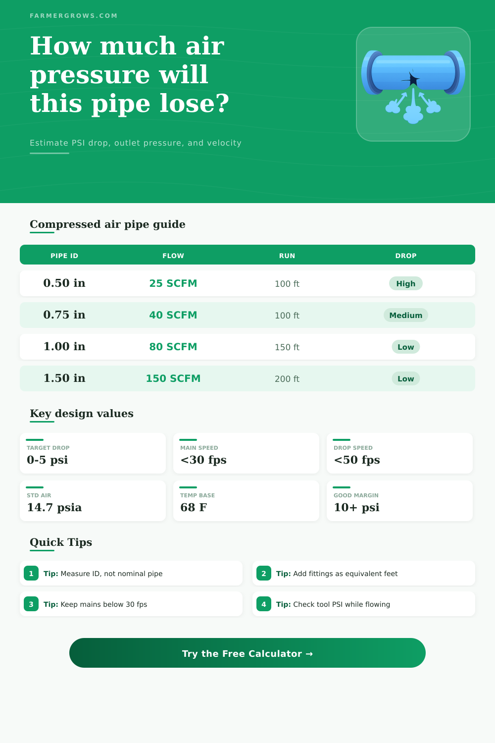
| 0.50 in | 25 SCFM | 100 ft | Often too much loss for steady tools |
| 0.75 in | 35 SCFM | 125 ft | Moderate loss for one work bay |
| 1.00 in | 60 SCFM | 150 ft | Good shop header starting point |
| 1.25 in | 100 SCFM | 200 ft | Better for long farm-shop loops |
| 1.50 in | 150 SCFM | 250 ft | Stable main for several drops |
| Fitting or Device | Simple Allowance | When to Increase It | Pressure Loss Reminder |
|---|---|---|---|
| 90 degree elbow | 3-8 pipe diameters | Tight-radius or threaded elbows | Several elbows can equal a long straight run |
| Tee through run | 5-10 pipe diameters | Air turns through branch opening | Branch tees are usually more restrictive |
| Ball valve full port | 1-3 pipe diameters | Partly closed or reduced-port valve | Valve bore can be smaller than pipe ID |
| Filter/regulator | Use rated chart | Dirty element or undersized bowl | Device drop may exceed pipe friction |
| Quick coupler | Use flow chart | High SCFM air tools | Small couplers can dominate total loss |
When air tools lose power during a cutting operation, the pipe that delivers the air to the tool usually causes the loss of power. Each elbow in the pipe, each foot of pipe, and each change in the diameter of the pipe can lead to a loss of air pressure in that pipe. The more these elements are used, the greater the loss of air pressure within that air tool.
Thus, before any new pipe are installed or an existing pipe drop is moved, the shop should of calculate the loss of air pressure within that pipe. To calculate the loss of air pressure, the shop must provide several different inputs. The inside diameter of the pipe is the first and, arguably, the most important calculation.
How to Check Air Pressure Loss in Shop Pipes
While two pipes may have the same nominal size, their inside diameter may differ by more than a quarter inch. The length of the pipe is the second calculation. The length includes any distance between the tool and the manifold, or between the tool and the receiver.
The length is treated as if it were a single length, since the other inputs account for the length of the individual elbows, tees, or valves in the system. The flow demand for the tool is entered in the units of SCFM (thousands of cubic feet per minute). The line pressure and the temperature of the compressed air within the shop automatically convert this value into actual cubic feet per minute.
The inlet pressure is the starting pressure of the air within the system, while the required tool pressure is the ending pressure of that air after it passes through the tool. The material from which the pipe is made can impact the roughness of that pipe, and there are lists of common pipe materials in the pressure loss calculator. Pipes made from black steel or galvanized pipe tend to be more rough than pipes made from copper or aluminum.
As a result, the pressure drop within black steel or galvanized pipes will be greater than within copper or aluminum pipes. However, that difference in pressure drop is small if the length of the pipe is short, but likely to be significant in long header pipes that supply many cutting bays within the shop. The output of the calculator include three different values.
The first is the loss of air pressure within the system. The second is the outlet (delivery) pressure within the system, which the calculator calculates as the inlet pressure minus the pressure loss. The outlet pressure is the pressure that the air tool will experience while in operation.
The third value is the margin of pressure that exists above the minimum pressure required by the air tool. A negative value for this parameter indicates that the air tool will not recieve enough pressure to perform its function. The velocity in the pipe is provided in the units of feet per second.
A reference table allows the shop to determine whether this velocity of air within the pipe is an acceptable rate for mains, branches, and short drops. Real shops are rarely as clean and well-regulated as the pressure loss calculation assumes. Air filters can fill with debris, the bores of quick couplers can differ from one another, and the regulators can drop the pressure of the air supplied to the tools.
While the air pressure loss calculator does not take into account the effects of these items, it does provide a realistic estimation of the pressure that will be supplied to the tools if these factors are considered. For instance, if the shop calculates the air pressure loss to be five or six psi before it reaches the first filter in the line, the shop knows that there is a marginal supply of air to that tool. However, if the calculated pressure loss is only two psi and the velocity of the air is thirty feet per second or less, there is room in the system to install filters or extend the length of any supply hose.
Furthermore, while air tools may be started with cooler air from the aftercooler within the air compressor, that air will warm within the supply hoses. Additionally, the warming air will expand within the hoses, increasing the velocity of the air movement through the hoses. This additional movement of air will create further pressure loss within the hoses.
Thus, while the shop can determine that the air supply hoses will function well during the winter months, they may not during the summer. The temperature input within the calculator allows shops to compare the air supply performance during winter and summer months. Additionally, elbows, tees, and valves in the air hose system will create additional resistance to the movement of air through those hoses.
Each of these fittings will have a specified length that can be entered into the calculator in an allowance for the pressure loss that they will create. Thus, the length of the air supply hose will likely have to be increased to account for the length of individual elbows or other fittings. Threaded fittings will create more loss of air pressure than welded or press-fit fittings.
Similarly, ball valves with smaller bores than those required to allow the full passage of air will create turbulence in that air movement. Additionally, turbulence in the movement of air will create additional loss of air pressure. Thus, the allowance for fittings within the calculator is one that should be entered into the calculator to determine whether the air supply system will function well, or whether the air supply hoses need to be changed to larger diameter.
Yet there are some common mistake with which shop workers are likely to be familiar when performing air pressure loss calculations. For instance, many individuals will measure the nominal size of the pipe rather than it’s inside diameter. Furthermore, individuals may measure the static pressure rather than the dynamic pressure that the tool will experience while in operation.
Additionally, the static pressure supplied to the tool by the receiver will not account for the friction loss within the supply hoses that are located upstream of the receiver. Finally, individuals may not account for the increase in total flow and pressure loss that will occur if another air tool is installed within the shop. In either case, it is always a good idea to calculate the pressure loss along the longest and busiest paths for air tools within a shop.
Additionally, the shop should compare the outlet pressure of the air within the supply lines to the pressure requirement of the most demanding air tool in the shop. If there is a comfortable margin of excess air pressure, then the supply lines will be able to handle the effects of temperature changes and future additions to that supply system. Furthermore, if the available air pressure is only a thin margin above the requirements of the most demanding air tool, the shop should increase the inside diameter of the air supply hoses.
An increase in the inside diameter of the supply lines will allow for more air to reach each air tool. The size of the compressor does not matter if the air pressure cannot make the trip from the compressor to the air tools. People dont like it when the pressure drops alot.
Youll need to check the pipes size too. Its important to realize that modern pipes is different than older ones. Many workers finds that they cant get enough air if the system is poorly designed.
They’re should be careful with the length of the hoses. The equipment needs to be moddern and well maintained. If you use a smaller pipe then the pressure will drop too fast.
One should check if the machine can absorbs the air flow. The shop workers needs to be careful. The rougness of the pipe is a big factor.
If the pipes is too long, then the pressure will be lost. The air flow can be unpredicatable. One should check the connection for any leaks.
The air tools needs regular maintenance. The diameter of the pipe is important for teh system. It is easy to make a mistake with the calcualtion.
The shop should check the air pressure more often. This is more important then most people think. One should always use the right tools for the job.
Making sure the air is clean is also very important. The pressure loss can be alot if you dont plan ahead. The pipes should be installed correctely.
This is a common problem in many shops.