🔧 Hydraulic Cylinder Rod Buckling Calculator
Check critical buckling load, safe working load, and required rod diameter from pressure, span, and end condition.
Buckling Output
Critical load is the lower of the Johnson and Euler results. The design force is the larger of the entered load and the hydraulic push force.
Calculation Breakdown
| End condition | K factor | Typical joint | Notes |
|---|---|---|---|
| Fixed-fixed | 0.50 | Both ends restrained | Highest buckling resistance |
| Fixed-pinned | 0.70 | Clevis to gland | Common cylinder layout |
| Pinned-pinned | 1.00 | Free rotation both ends | Use for simple pivot support |
| Fixed-guided | 0.70 | Guided end slide | Rotation limited by guide |
| Fixed-free | 2.00 | Cantilevered rod | Worst buckling case |
| Material | Modulus E | Yield strength | Typical use |
|---|---|---|---|
| Chrome-plated 1045 steel | 29.0 Mpsi | 77 ksi | General purpose rods |
| Induction-hardened 4140 | 29.0 Mpsi | 110 ksi | Higher fatigue life |
| Quenched and tempered 4140 | 29.0 Mpsi | 145 ksi | High strength rod stock |
| Nitrided alloy steel | 29.0 Mpsi | 115 ksi | Wear resistant surface |
| 17-4 PH stainless | 28.0 Mpsi | 145 ksi | Corrosion resistant rods |
| 316 stainless steel | 28.0 Mpsi | 30 ksi | Corrosion first, strength second |
| Bore | Area | Force @ 3000 psi | Force @ 250 bar |
|---|---|---|---|
| 1.5 in | 1.77 in2 | 5,301 lbf | 6,408 lbf |
| 2.0 in | 3.14 in2 | 9,425 lbf | 11,391 lbf |
| 2.5 in | 4.91 in2 | 14,726 lbf | 17,799 lbf |
| 3.0 in | 7.07 in2 | 21,206 lbf | 25,630 lbf |
| 4.0 in | 12.57 in2 | 37,699 lbf | 45,565 lbf |
| 5.0 in | 19.63 in2 | 58,905 lbf | 71,195 lbf |
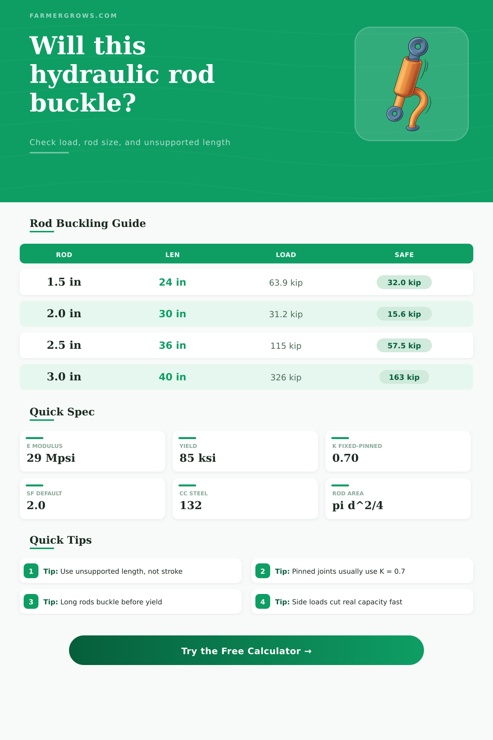
| Rod diameter | Critical load | Safe load | Slenderness |
|---|---|---|---|
| 1.00 in | 44,376 lbf | 22,188 lbf | 67.2 |
| 1.25 in | 81,928 lbf | 40,964 lbf | 53.8 |
| 1.50 in | 127,825 lbf | 63,912 lbf | 44.8 |
| 1.75 in | 182,066 lbf | 91,033 lbf | 38.4 |
| 2.00 in | 244,653 lbf | 122,326 lbf | 33.6 |
| 2.50 in | 394,860 lbf | 197,430 lbf | 26.9 |
| 3.00 in | 578,447 lbf | 289,224 lbf | 22.4 |
Rod buckling occurs when a slender rod is compressed, yet the rod cannot remain straight. Rod buckling occurs when the rod deflects sideways instead of getting crushed by the weight of the loads. A hydraulic rod can buckle if the rod is too long and thin or if a high compressive force subjects the hydraulic rod.
Hydraulic engineers must understand rod buckling because buckling of the hydraulic rod can ruin the whole equipment and cause the equipment to fail. The length of the rod is a critical aspect of rod buckling. The unsupported length of the hydraulic rod is the distance between the two points of support for the rod.
Why Hydraulic Rods Buckle and How to Check Them
Many times, engineers makes a mistake when they use the total stroke of the cylinder as the unsupported length of the rod. To find the unsupported length, you must measure the distance from the pin center of the rod to the point of restraint. The longer the unsupported length of the rod, the more likely the rod is to buckle.
The end conditions of the rod determine how much resistance the rod puts up against buckling. For hydraulic rod end conditions, if the rod is fixed at the gland or bearing and pinned at the clevis, it will have a higher resistance to buckling than if it was free to swivel at both ends of the rod. The effective length of the hydraulic rod, represented by the K value, will be lower for a fixed-fixed rod than for a pinned-pinned rod.
The lower the K value, the more high load that can be carried by the rod without buckling. Worn bushings or misaligned clevises can increase the K value of the rod, and an increased K value will reduce the load carrying capacity of the rod. The material out of which the rod is manufactured has a bearing on the strength and stiffness of the rod.
For instance, manufacturers use chrome-plated 1045 steel for general duty because the steel has a solid yield strength for general use. For heavy push applications, quenched 4140 steel will have a higher yield strength. For marine work, stainless steel is used because it resists corrosion, although it may not be the best material for heavy load applications.
Depending on the slenderness ratio of the rod, either the Johnson formula or the Euler formula can be used to calculate the buckling limit of the rod. You must use the correct material for the rod because using the wrong material will result in the rod either buckling or yield under load. The slenderness ratio of the rod dictates which equation will be used to calculate the limit at which the rod will buckle.
The slenderness ratio can be calculated by dividing the effective length of the rod by the radius of gyration of the rod. For a round rod, you can calculate the radius of gyration by dividing the diameter of the rod by four. If the slenderness ratio of a rod is below 130, the Johnson formula will be used to calculate the limit of the rod.
For rods with a slenderness ratio above 130, the Euler formula will be used to calculate the limit of the rod. Short and fat hydraulic rods will crush straightly. Long and skinny hydraulic rods will tend to bend sideways.
In addition to calculating the rod’s buckling limit, you must also calculate the hydraulic push force because it will usually be higher than the external load on the rod. A 2.5-inch diameter hydraulic cylinder at 3000 psi will generate over 14,000 pounds of hydraulic push force. Such a high load can be used to test whether a rod of a lower diameter is sized appropriately for the job.
Side loads can cause rod buckling. Misalignment of the rod or worn guides in the cylinder can cause side loads. Introducing a side load or bending load on a hydraulic rod will reduce its buckling load by half or more.
Vibrations caused by heavy machinery can also contribute to rod buckling. Machines like loaders that vibrates when they move over rocks can contribute to rod buckling. In these cases, a higher safety factor than normal is required.
Rods with hollow centers or with pins that are offset from the center of the rod are weaker than solid rods with center pins. In these cases, rods can be treated as if they have a more higher slenderness ratio. A calculation tool can be used to determine whether the hydraulic rod will remain within a safe limit.
For instance, the user can enter the diameter of the rod, the unsupported length of the rod, and the rod material into a rod buckling calculator. The calculator will calculate for the user the limit of the rod using the appropriate formula. The critical load that the rod can take without buckling will be calculated.
The allowable load after application of a safety factor will be calculated. If the hydraulic rod’s utilization percentage is over 100%, the rod is not safe and needs to be resized. There are some common mistakes that engineers must avoid when calculating whether a hydraulic rod will buckle.
One of the mistakes is to use the total stroke of the cylinder instead of the unsupported length of the rod. The engineer must not overestimate the fixity of the end conditions of the rod. Another mistake is to ignore the force that the hydraulic fluid exert on the piston.
This force is usually much higher than any external load. Rod buckling usually occurs during the extension cycle of the rod. Buckling rarely occurs during the retraction cycle of the rod.
When designing hydraulic rods, there are several different tradeoffs to make. For example, increasing the diameter of the rod will make it more resistant to buckling, but it will also add more weight to the equipment. Additionally, using thicker rods will shorten the life of the seals.
Therefore, seal wear has to be taken into account. Using 4140 steel will last longer under heavy loads than 1045 steel, but 4140 is more expensive. In any case, rod diameter and material should always be started with solid numbers from calculations rather than using hydraulic rod prototypes that may fail during operation.
Using presets to calculate the parameters of a rod can be of great benefit to the designer of hydraulic equipment. For instance, a log splitter machine will have a fixed-free rod end condition with a K value of 2.0; engineers must be aware of the risk of cantilever rod buckling. A press clamp machine may have a fixed-fixed rod end with a lower K value.
The user will have to set the preset parameters according to the different requirements of each machine. By performing a check for rod buckling, the designer can build confidence in the machine; otherwise, the check for rod buckling will ensure that the hydraulic rod can handle the required peak pressure.