Water Pump GPM Calculator
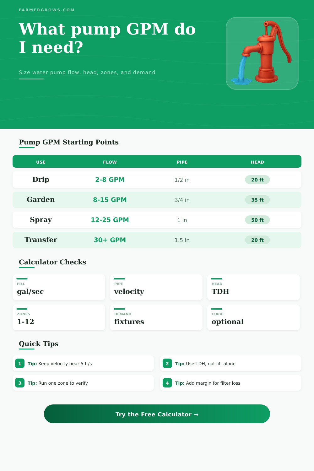
Estimate pump flow from a timed fill test, pipe diameter, pressure, elevation head, friction, pump curve mode, active zones, fixture demand, emitter demand, and efficiency.
Use this as a planning check for irrigation, garden transfer, greenhouse zones, livestock tanks, and utility pumps. Final pump selection should be verified against the actual pump curve at your total dynamic head.
Pump Flow Results
The cards compare measured fill flow, calculated demand, pipe velocity, and total dynamic head so you can check the pump against both flow and head.
| Pipe ID | About 3 ft/s | About 5 ft/s | About 7 ft/s |
|---|---|---|---|
| 1/2 inch | 2.3 GPM | 3.8 GPM | 5.3 GPM |
| 3/4 inch | 5.2 GPM | 8.6 GPM | 12.1 GPM |
| 1 inch | 9.2 GPM | 15.3 GPM | 21.4 GPM |
| 1 1/4 inch | 14.4 GPM | 23.9 GPM | 33.4 GPM |
| 1 1/2 inch | 20.7 GPM | 34.4 GPM | 48.2 GPM |
| 2 inch | 36.7 GPM | 61.2 GPM | 85.6 GPM |
| TDH piece | Formula used | Typical range | Why it matters |
|---|---|---|---|
| Pressure head | PSI x 2.31 | 23-115 ft | Sprinklers, regulators, and nozzles need pressure after all losses. |
| Static head | Elevation change | 0-80 ft | Lifting water higher increases required pump head directly. |
| Suction lift | Source to pump inlet | 0-20 ft | Surface pumps lose prime and capacity as suction lift increases. |
| Friction head | Run x chart loss / 100 | 2-60 ft | Small pipe and long hose can erase advertised pump GPM. |
| Filter and valve loss | Added allowance | 3-25 ft | Filters, regulators, valves, and backflow devices add head. |
| Application | Main formula | Common inputs | Practical check |
|---|---|---|---|
| Sprinkler zone | Heads per zone x nozzle GPM | 4-12 heads, 0.8-3 GPM each | Use the nozzle chart at target PSI, not just the head body size. |
| Drip zone | Emitters x GPH / 60 | 50-500 emitters, 0.25-2 GPH | Filter loss and pressure regulation matter more than raw flow. |
| Hose or transfer | Timed fill GPM x margin | 5 gal bucket or known tank | Repeat the fill test at the actual hose length and nozzle setting. |
| Tank refill | Tank gallons / target minutes | 50-500 gal tanks | Float valves may need minimum pressure to flow at rated capacity. |
| Multi-zone manifold | Largest simultaneous zone total | 1-4 active zones | Do not add every zone unless they truly run at the same time. |
| Pump type | Good fit | Typical strength | Limit to watch |
|---|---|---|---|
| Submersible utility | Transfer, drain, pond drawdown | High flow at low head | Often weak at sprinkler pressure. |
| Shallow well jet | Garden booster, well draw, tanks | Moderate pressure and flow | Suction lift must stay reasonable. |
| Booster pump | Irrigation pressure boost | Maintains pressure at demand | Needs adequate inlet supply. |
| Centrifugal transfer | Fast moving between tanks | Efficient bulk movement | Performance drops as head rises. |
| Diaphragm demand | Small sprayers, RV, low-flow lines | Pressure switch control | Lower continuous GPM than transfer pumps. |
Check the curve at your TDH. A pump advertised at 40 GPM may deliver far less once it has to provide 40 PSI, lift water uphill, push through filters, and overcome long pipe friction.
Resize pipe before oversizing the pump. If velocity is high, a larger pipe or shorter hose can restore usable GPM, reduce noise, and lower the head the pump must fight.
A flow calculation are the mathematical process for determining how many gallon of water a pump will actualy deliver to the system. The pump may states how many gallons of water it will deliver, but the actual number of gallons may differ due to various variable in the system. A flow calculation is necessary to account for these variables and ensure that the irrigation system perform correctly.
The best way to calculate the flow of water from the system is to perform a fill test. To perform a fill test, you will need to filling a bucket or tank for a specific number of second. You will then divide the number of gallons of water that were collected by the number of seconds it take to fill the tank.
How to Calculate Water Flow for an Irrigation Pump
This will provide you with an idea of the flow of the pump under current conditions. However, this is only one part of the system. The flow of the water will change based on the length of the hose, the presence of a filter, or the height of the outlet.
A flow calculation allow you to calculate the effect of each of these variables before installing the system. Another important variable to consider is the size of the pipe. The size of the pipe will impact the speed at which water travels through the system.
If the water speed up through the system, the friction between the water and the pipes will increase. An increase in friction will reduce the amount of water pressure in the system. To avoid this issue, you can perform a velocity check to ensure the speed of the water are within an appropriate range.
Too slow of a speed in the system will not provide enough water pressure to the nozzles of the system. Too fast of a speed will create the same issue as the friction between the water and the system will force the pump to create more greater head pressure. A flow calculation will allow you to account for these issues regarding the size of the pipes before installing them into the system.
In addition to the size of the pipes, another important calculation is the total dynamic head of the system. The total dynamic head is represent by the amount of vertical rise in the system, the amount of lift the pump must perform to draw in water, the friction in the system, and the amount of head loss due to filters. Each foot of vertical rise in the system will use some of the pressure of the pump.
Each pound per square inch of the water pressure at the outlet of the pump is also some of the total dynamic head of the system. You must compare the total dynamic head to the manufacturer specifications for the pump to ensure it is sufficient for the system. Due to certain head losses in the system, the pump that may have a high delivery rate may fail to meet the demands of the irrigation system.
The demand of the system will change according to the particular task that the water performs. For instance, if the system include drip zones, the demand for water will be low because drip emitters release small amount of water. However, if the system also include spray zones, there will be a higher demand for water because the spray nozzles release more water than the drip emitters.
If there are multiple zone that are to be irrigated at the same time, the pump will have to handle the demands of the zone with the highest rate of water requirements. In addition to considering the particular demands of the zones within the system, you should also consider the duty factor of the zones. Some zones may be cycling on and off, such as a livestock trough that will be refilled numerous times during the day, but other zones may be on for longer periods of time, such as a mist bench in a greenhouse that will remain in operation for extended periods of time.
Thus, the calculations for each of these zone will need to be adjusted to compensate for these different demands. Efficiency of the pump should also be considered in the calculations. Pumps dont often reach the maximum efficiency of the pump.
Factors that can impact the efficiency of the pump include the voltage supply to the pump, the cleanliness of the pump filters, and the wear of the pump impellers. Therefore, a percentage that reflects the efficiency of the pump should be included in the calculations to determine the actual water flow that will be delivered to the irrigation system. Additionally, a margin percentage should also be included in the calculations.
For instance, if the margin percentage is 10%, this provides extra capacity to the system in the instance that the filter is dirty, or that the weather during the growing season creates different evaporation rate than those that are calculated. A common mistake in the irrigation system is to purchase the pump first and then to determine the size of the pipes second. This is a mistake because if the velocity of the water through the system is too high, a larger diameter pipe should be used rather than using a larger pump.
Another common mistake is to ignore the suction lift that the pump will have to perform. Pumps can lose the capacity that they are designed to have if the suction lift is too high. Thus, the flow calculation for an irrigation system will help to avoid these mistakes.
Finally, the pump curve for the pump should be used to understand the performance of the pump. The pump curves for irrigation systems may indicate the flow that the pump will achieve when the head is zero, but that flow is not the same as the flow that will exit the sprinklers when there is pressure placed on the system. The flow calculation will allow for the pump curve to be read at the total dynamic head that will be create by the irrigation system.
By reading the pump curve and the flow calculation for the system, the manufacturer can be certain that the pump has enough capacity to handle the demands of the system, and that the pipes has the correct size to supply the water to each zone.