Wind Turbine Blade Size Calculator
Estimate swept area, rotor diameter, blade length, and TSR rotor speed from target watts, wind speed, air density, Cp, generator efficiency, hub diameter, and safety margin.
The main sizing step is target power divided by wind power per square meter after the rotor Cp and generator efficiency are applied. The result is the swept area needed at the selected wind speed.
Blade Size Estimate
Results are based on swept area: P = 0.5 × rho × A × V³ × Cp × generator efficiency.
Where q is available wind watts per m² after Cp and generator efficiency.
Diameter is sqrt(4A / pi). Blade span is based on half that circle.
Higher TSR means faster tips and RPM for the same wind and radius.
Three-blade rotors balance starting, smoothness, and efficient lift.
| Design wind | Power in wind | Usable at Cp 0.35, 85% | Area for 1 kW plus 15% |
|---|---|---|---|
| 5 m/s (11.2 mph) | 76.6 W/m² | 22.8 W/m² | 50.5 m² |
| 6 m/s (13.4 mph) | 132.3 W/m² | 39.4 W/m² | 29.2 m² |
| 7 m/s (15.7 mph) | 210.1 W/m² | 62.5 W/m² | 18.4 m² |
| 8 m/s (17.9 mph) | 313.6 W/m² | 93.3 W/m² | 12.3 m² |
| 10 m/s (22.4 mph) | 612.5 W/m² | 182.2 W/m² | 6.3 m² |
| Rotor or drive condition | Typical Cp | Generator efficiency | Use in calculator |
|---|---|---|---|
| Well-shaped 3-blade lift rotor | 0.35 to 0.45 | 85% to 92% | Good design target |
| Homebuilt wood or PVC blades | 0.20 to 0.32 | 70% to 85% | Conservative sizing |
| High-solidity farm rotor | 0.18 to 0.30 | 70% to 88% | Slow, high starting torque |
| Drag-style vertical rotor | 0.10 to 0.22 | 65% to 82% | Needs larger area |
| Blade count | Usual TSR range | Typical use | Design note |
|---|---|---|---|
| 2 blades | 6 to 9 | Fast small HAWT | Light rotor, more vibration care |
| 3 blades | 5 to 8 | General wind turbine | Balanced efficiency and smoothness |
| 4 to 6 blades | 3 to 6 | Pumps and quiet rotors | More solidity, lower speed |
| 12+ blades | 1 to 3 | Farm water-pump rotor | High starting torque, low RPM |
| Target output | Wind speed | Assumptions | Approx rotor diameter |
|---|---|---|---|
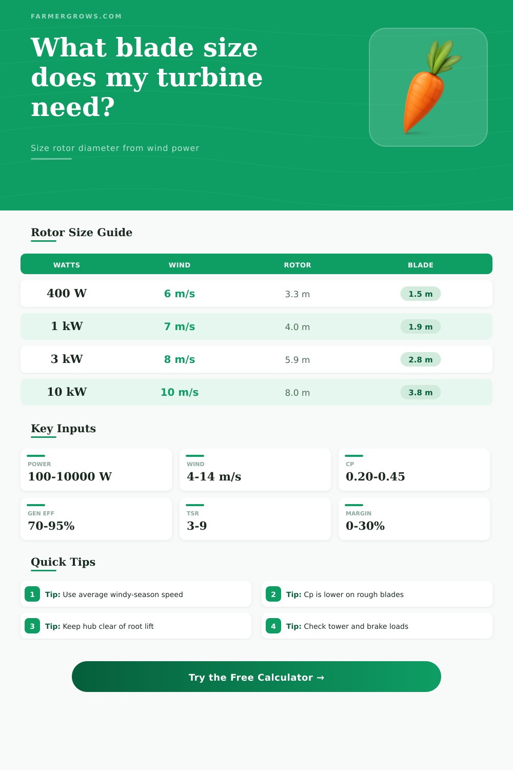
| 100 W | 6 m/s | Cp 0.30, eff 80%, margin 15% | 1.9 m / 6.2 ft |
| 400 W | 6.5 m/s | Cp 0.32, eff 82%, margin 15% | 3.3 m / 10.8 ft |
| 1,000 W | 7 m/s | Cp 0.35, eff 85%, margin 15% | 4.8 m / 15.7 ft |
| 3,000 W | 8 m/s | Cp 0.38, eff 88%, margin 15% | 6.8 m / 22.3 ft |
| 10,000 W | 10 m/s | Cp 0.40, eff 90%, margin 15% | 8.1 m / 26.6 ft |
Best fit for most battery and grid-tie horizontal-axis builds.
Use moderate Cp and TSR around 5 to 8.
Can be lighter and quick, but balance and yaw behavior matter more.
Use higher TSR and verify tip speed.
Strong low-speed starting for pumps and mechanical loads.
Use lower TSR and conservative Cp.
Simple and tolerant of shifting wind, but needs much more area.
Use low Cp when estimating blade size.
In order to provide a specific amount of power from the wind to an battery, it is first important to determine the necessary diameter of the rotor. The diameter of the rotor can include a variety of factor beyond size alone. The diameter of the rotor depend upon the efficiency with which the blade can perform moving air into torque, as well as the efficiency of the generator to perform that torque into electricity.
Additionally, it is also necessary to incorporate a safety buffer into the calculation for the rotor diameter, since the actual strength and conditions of the wind will be different than those calculated for the design of the machine. The energy that is contained within the moving wind is proportional to the cube of the wind speed. Thus, one small increase in the speed of the wind will lead to a much larger increase in the amount of energy that the rotor can capture.
How to Choose the Rotor Size for a Wind Turbine
Consequently, the smaller rotor diameter can be employed when moving from a location of the wind to a location of the open ridge or mountains pass, where wind speeds will be more greater. In the opposite situation, though, where the measured wind speeds are lower than expected, the diameter of the rotor will have to be larger than would be calculated through a simple relationship between wind speed and rotor diameter. Thus, this factor related to the cubic relationship between speed and energy is one of the most important in assessing the site of a proposed wind turbine installation.
The power coefficient of the rotor, represented as Cp, determines the percentage of the energy contained within the moving air that the rotor will be able to capture. No rotor can ever reach the theoretical maximum of the coefficient of performance of 59 percent, but small rotors typically has a coefficient of performance between 25 and 40 percent. This percentage of the energy of the wind that is captured is lost due to factors like tip losses, roughness of the blade surface, and differences in the angle of attack of the different portions of the rotor disk.
Furthermore, the efficiency of the generator to transform that mechanical power into electrical energy will also have a major impact on the amount of energy that can be delivered to the battery; even good permanent-magnet alternators lose energy at a rate of 90 percent of the available mechanical power, and home-built alternators may lose as much as 25 percent of that power due to wiring and rectification losses. Thus, the product of the Cp and the generator efficiency will impact the amount of energy that reaches the battery. Because the calculator is based upon a target energy output from the machine, alterations to the parameters of the machine will alter the required diameter of the rotor.
For instance, increasing the efficiency of the rotor or the generator will allow for a reduction in the required diameter of the rotor. Similarly, any increase in the safety margin of the rotor will require an increase in the diameter of the rotor. A 15 percent safety margin is typically used for wind turbines that are periodically inspected to ensure they remain in good operating condition; 25 percent is used for locations that experience heavy amounts of pollen, salt spray, or icing.
The number of blades on the rotor, as well as the tip-speed ratio of the rotor, are two additional factors that will impact the performance of the wind turbine. Two-blade rotors has higher tips and rpm ratings, but have to be constructed to eliminate imbalances of the rotor. Three-blade rotors are the most common design, though; three-blade rotors have a better balance between starting torque, smoothness of the rotor, and efficiency.
Higher blade counts indicate a reduction of the tip-speed ratio and starting torque, but also a reduction of the noise created by the rotor. These factors can be entered into the calculator to determine the effect that the number of blades will have upon the rpm of the rotor given the diameter of the rotor. The density of the air is another factor in the calculation of the energy output of the rotor.
The power of the rotor scales in direct relationship to the density of the air. At sea level, air density is roughly 1.225 kg/m^3. At altitudes of 1500 meters, though, the air is thinner and contains less energy.
Thus, the rotor diameter will have to be larger at these altitudes. Similarly, changes in the temperature of the air will also change the density of the air. Thus, modifications to the altitude and temperature of the site will require consideration of the air density of the location.
The diameter of the hub of the rotor is another factor that will impact the diameter of the rotor; blade length is measured from the hub of the rotor to the tip of the blade. Thus, the larger the diameter of the hub, the smaller the diameter of the rotor itself. In extreme cases, where the diameter of the hub is too large to the diameter of the rotor, the blades may not have enough relative wind speed to provide the necessary lift to the blades to allow them to turn.
Thus, this factor should be considered in that the hub diameter should be 30 percent of the rotor diameter at most for lift-type machines. Once the rotor diameter is determined, additional considerations must be made for the structure of the rotor. For instance, the rotor must have sufficient space for mounting to the tower, the blades must be stiff enough to perform their tasks, and the rotor must be able to handle overspeed conditions.
A rotor of a given diameter may be sized for wind speeds of 7 meters per second (m/s), but may experience wind speeds of 14 m/s. Therefore, the control system for the rotor must be able to handle those increased speeds so that the tower does not need to be constructed to endure those high speeds. Additionally, the wind is rarely steady; turbulent winds created by trees, buildings, and the tower itself will reduce the efficiency of the rotor. Furthermore, such turbulence can lead to vibrations of the blades at high speeds.
Therefore, the location of the wind turbine should be carefullyly considered to minimize the impact of these factors. A safety margin can be used to compensate for the differences between wind tunnel tests of the structure of the rotor and the actual winds that will be experienced at the site of the turbine installation. The construction of the blades will impact the efficiency of the rotor; wooden and PVC blades will never achieve the same efficiency as molded composite blades.
Thus, any reduction in the efficiency of the blades will require an increase in the diameter of the rotor to provide the same amount of energy to the battery as intended. For instance, if the blades have a power coefficient of 0.35, but drop to a value of 0.28, 25 percent of the area of the blades will have to be increased to provide the same amount of power output to the battery. Finally, the efficiency of the generator and the battery, as well as the load placed upon the battery, will influence the performance of the entire machine.
For instance, if the goal of the machine is to charge a battery, the generator will have to exhibit high efficiency at a variety of rpm levels; it will not operate at full power most of the time. Thus, the diameter of the rotor will set the limit to the amount of energy that is made by the machine, but the efficiency of the generator and load will determine how much of that energy is actualy delivered to the end use. Thus, this calculator will determine the size of the rotor that will be required for the design of the machine.
Once the size of the rotor is determined, the design of the machine can begin; selecting the airfoils for the blades, determining the structure of the blades, and the furling mechanics of the blades can all begin.