Drainage Pipe Flow Calculator
Estimate pipe flow, velocity, total fall, and spare capacity for field drains, tile mains, culverts, and wet spots before you set pipe size.
Pick a common drainage situation to load a practical starting point. Each preset sets the unit system, diameter, length, slope, fill ratio, material, demand, and buffer.
Drainage Pipe Results
Enter the pipe diameter, slope, fill ratio, and material to see the estimated flow and reserve capacity.
Calculation Breakdown
| Material | Manning n | Flow feel | Best use |
|---|---|---|---|
| Smooth PVC | 0.009 | Lowest drag | Long clean mainlines |
| Solid wall HDPE | 0.011 | Low drag | General farm drains |
| Corrugated PE | 0.012 | Standard drain | Laterals and collectors |
| Clay tile | 0.013 | Traditional tile | Older field systems |
| Concrete pipe | 0.014 | Heavy mainline | Outlet and crossing runs |
| Steel pipe | 0.015 | Rougher wall | Short heavy duty lines |
| Size | Flow | Velocity | Typical use |
|---|---|---|---|
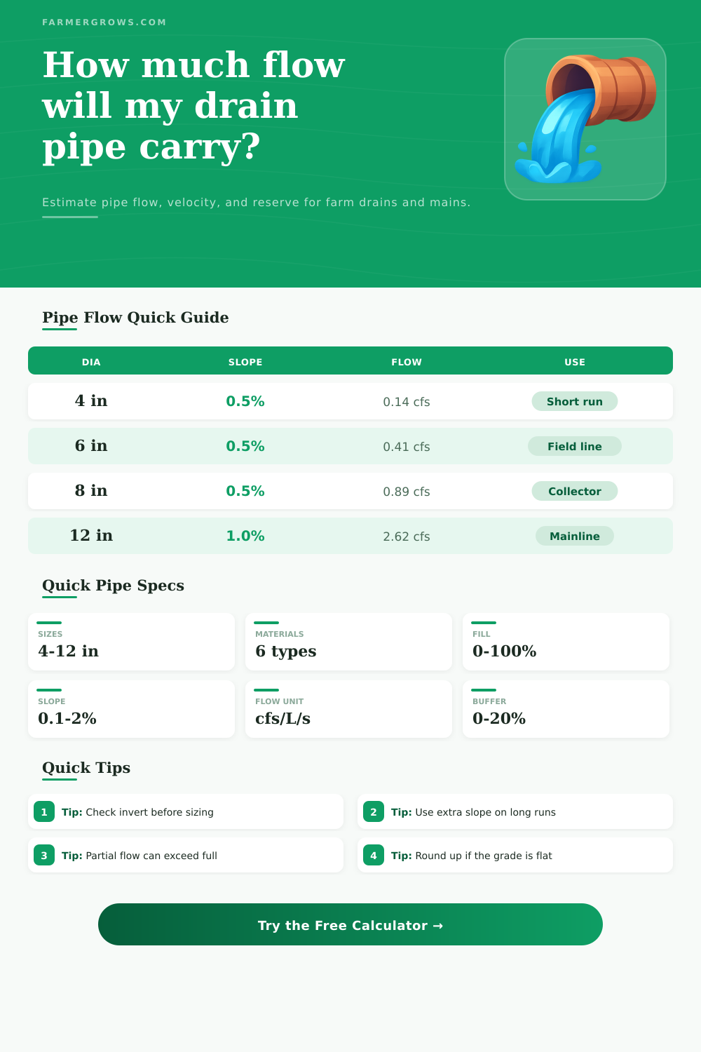
| 4 in / 100 mm | 0.14 cfs / 3.96 L/s | 1.64 ft/s / 0.50 m/s | Short lateral |
| 6 in / 150 mm | 0.41 cfs / 11.67 L/s | 2.17 ft/s / 0.66 m/s | Field line |
| 8 in / 200 mm | 0.89 cfs / 25.12 L/s | 2.63 ft/s / 0.80 m/s | Collector |
| 12 in / 300 mm | 2.62 cfs / 74.08 L/s | 3.44 ft/s / 1.05 m/s | Mainline |
| Fill | Area | Flow | Field note |
|---|---|---|---|
| 25% | 19.6% | 13.7% | Thin trickle |
| 50% | 50.0% | 50.0% | Half full |
| 75% | 80.4% | 91.2% | Strong flow |
| 90% | 94.8% | 106.6% | Peak zone |
| Grade | Fall per 100 ft | Fall per 30 m | Use case |
|---|---|---|---|
| 0.10% | 1.2 in | 30 mm | Very flat drain |
| 0.25% | 3.0 in | 75 mm | Light fall |
| 0.50% | 6.0 in | 150 mm | Common target |
| 1.00% | 12.0 in | 300 mm | Steeper line |
Effective field drainage require you to understand how water move through an pipe. The size and the slope of the drain pipe will determines the amount of water that the pipe will be able to carry. If the pipe is too small or if the slope of the pipe are too shallow, the field will not became drained effective.
Many people attempt to guess at the size of the field drain pipe that is required, however, mathematical principle can be utilized to determine the capacity that the drain pipe should have in relation to the field. The capacity of a pipe will depend upon the slope of the pipe, the size of the pipe, and the roughness of the material of the pipe. Pipes with a higher slope will allow the water to move fast through the pipe due to the gravitational pull on the field and the slope of the pipe.
How to Choose the Right Field Drain Pipe
Smooth materials will allow the water to move faster through the pipe than rough materials due to less friction between the water and the pipe material. For instance, PVC drain pipes are smooth material while corrugated plastic drain pipes are rough materials. The flow rate of water through the field drain pipe can be calculated by utilizing Mannings equation, which takes into account the roughness of the pipe, the size of the pipe, and the slope of the pipe.
The result of Manning’s equation will be the flow rate of water in units of cubic feet per second or liter per second. The selected material of the pipe is important and the wrong material may result in inaccurate calculation. For instance, if a rough pipe material was selected instead of a smooth material, the flow rate will be calculated to be lower then they should of be.
Another factor to consider is the fill ratio of the pipe. It is a common misconception that pipes carry the most water when they are completely fill with water. However, pipes can carry more water when they are filled to a three-quarter level.
When pipes are completely filled with water, the water experience friction against the top of the pipe, which slows the movement of the water through the pipe. When the pipe is only filled to a three-quarter level, the water moves more efficient through the pipe. Three-quarters fill ratio are, therefore, targeted for drainage field pipes.
In addition to the fill ratio of the pipe, it is also important to consider the length of the pipe and the total fall of the pipe. The total fall of the pipe will impact the elevation of the inlet and the outlet of the pipe. A surveyor can survey the outlet of the field pipe first, and then the survey can proceed backward to the inlet of the drainage field pipe.
If the elevation of the outlet of the field drain pipe is incorrectly set, the field drain pipe will not have a proper slope to efficiently drain the field. Another factor of a field drain pipe is the velocity of the water through the pipe. The velocity should be at least two feet per second.
If the velocity is too slow, the silt that is within the field may settle in the pipe and eventually contribute to clogging of the pipe. However, if the velocity is too fast, the water may erode the joint of the pipe over time. The velocity of water can, therefore, be balanced to allow for self-cleaning pipes without erosion of the joints of the pipe.
Finally, it is important to add a buffer to the calculations for field drainage. Factors of the field and the environment will change how much water that drains through the pipe. A ten percent buffer can be added to the calculations for both silt that may fill the pipe and for the settling of the soil grade over time.
If the size of the pipe, the material of the pipe, and the slope of the pipe are all matched to the requirement of the field, the field drainage will function corectly.